Laser multiplex transmission apparatus

A multi-channel transmission and laser technology, which is applied in the direction of lasers, transmission systems, mechanical equipment, etc., can solve the problems of difficult optical multi-channel transmission of beams, reduction of coupling efficiency of beams to optical fibers, etc., and achieve the effect of high transmittance

Inactive Publication Date: 2004-08-18
FUJIFILM CORP
View PDF6 Cites 16 Cited by
  • Summary
  • Abstract
  • Description
  • Claims
  • Application Information

AI Technical Summary

Problems solved by technology

Therefore, in this case, after the entire beam is converged, it is difficult to accurately realize the optical multiplexing of the beam, and the coupling efficiency of the beam to the fiber is reduced

Method used


Image

  • Laser multiplex transmission apparatus
  • Laser multiplex transmission apparatus
  • Laser multiplex transmission apparatus

Examples


Embodiment Ex1

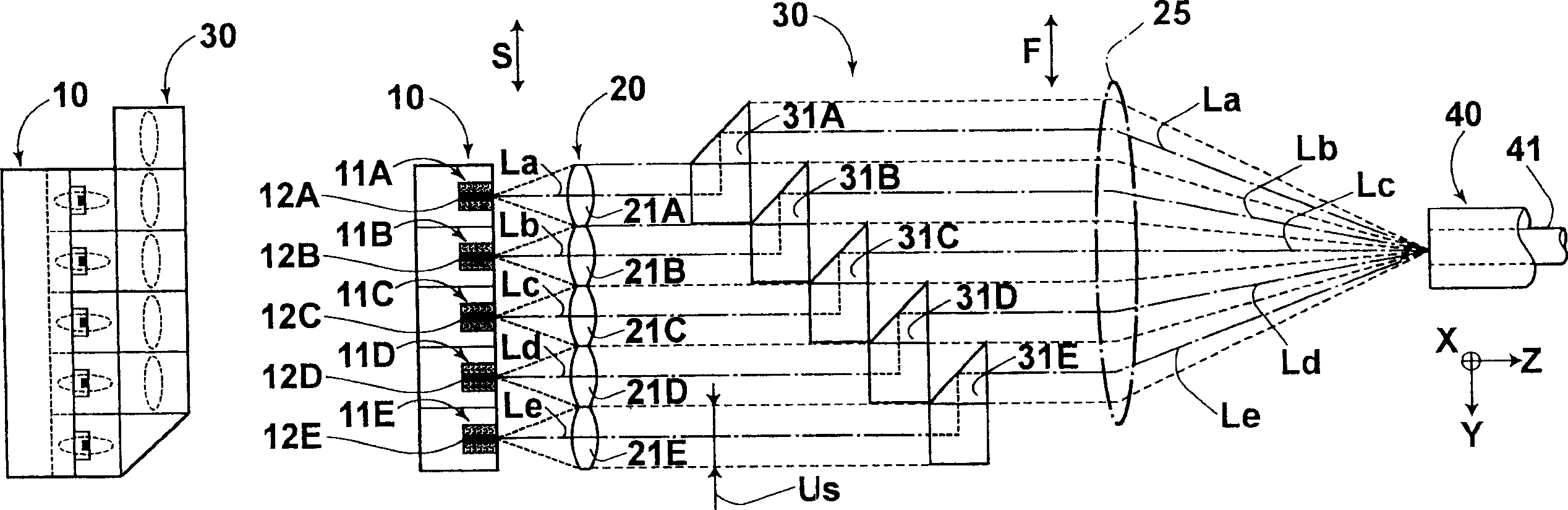
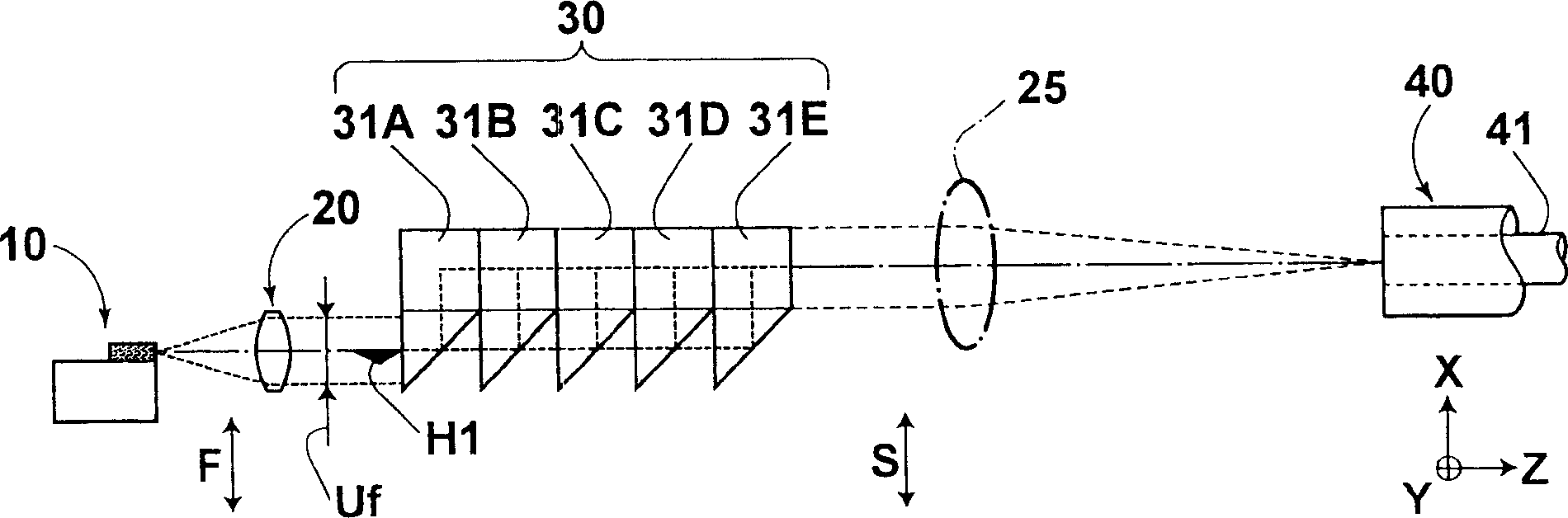
[0144] Figure 10A and Figure 10B A schematic configuration diagram showing the laser multiplexing device 101 according to Embodiment Ex1. Figure 10A is a plan view of the laser multiplexing device 101 . Figure 10B is a front view of the laser multiplexing device 101 . Figure 11 is a perspective view of a prism used in a beam rearrangement optical system.

[0145] The laser multiplexing apparatus 101 of Embodiment Ex1 includes: a laser block 111B' on which five semiconductor lasers are provided; a collimating optical system 111C; a beam rearranging optical system 111R; a converging optical system 111F;

[0146] It should be noted that, as described above, the light beams emitted by the five semiconductor lasers on the laser block 111B have an emission width Ds of 25 μm in the direction of the slow axis. The focal length of the converging optical system 111F is 30 mm in the fast axis direction and 2.85 mm in the slow axis direction. The core diameter of the optical fib...

Embodiment Ex2

[0153] Figure 12A and Figure 12B A schematic configuration diagram showing the laser multiplexing device 102 according to Embodiment Ex2. FIG. 12A is a plan view of the laser multiplexing device 102 . Figure 12B is a front view of the laser multiplexing device 102 . Figure 13 is a perspective view of a prism used in a beam rearrangement optical system.

[0154] The laser multiplexing apparatus 102 of Embodiment Ex1 includes: a laser block 112B′ on which five semiconductor lasers emitting light beams in the −Y direction are provided; a collimating optical system 112C; a beam rearranging optical system 112R; a converging optical system 112F ; and optical fiber 112L.

[0155] It should be noted that, as described above, the light beams emitted by the five semiconductor lasers on the laser block 112B have an emission width Ds of 25 μm in the direction of the slow axis. The focal length of the converging optical system 112F is 30 mm in the fast axis direction and 2.85 mm in ...

Embodiment Ex3

[0162] FIG. 14A and FIG. 14B show a schematic configuration of a laser multiplexing device 103 according to Embodiment Ex3. FIG. 14A is a plan view of the laser multiplexing device 103 . FIG. 14B is a front view of the laser multiplexing device 103 .

[0163] The laser multiplexing device 103 of Embodiment Ex3 includes: a laser block 113B provided with ten semiconductor lasers emitting light beams in the +Z direction; a collimating optical system 113C; a beam rearranging optical system 113R; a converging optical system 113F; and Fiber 113L.

[0164] It should be noted that the emission width Ds in the direction of the slow axis of the light beams emitted by the ten semiconductor lasers on the laser block 113B is 30 μm as described above. The focal length of the converging optical system 113F is 60 mm in the fast axis direction and 2.85 mm in the slow axis direction. The core diameter of the optical fiber 113L is 60 μm.

[0165] The beam rearranging optical system 113R incl...


PUM


Abstract

In a laser light multiplexing apparatus: a collimating optical system collimates light beams emitted from semiconductor lasers so that the slow axes of the light beams become coplanar, and optical axes of the light beams become parallel to each other; a light beam rearrangement optical system constituted by prisms respectively arranged in correspondence with the light beams rearranges the light beams in such a manner that directions of the fast axes of the light beams are changed at different locations along a direction in which the light beams propagate, and the fast axes of the light beams become coplanar; and a convergence optical system converges a bundle of the light beams rearranged by the light beam rearrangement optical system, in directions of the fast axes and the slow axes of the light beams, and makes the converged bundle of the light beams enter an optical fiber.

Description

technical field [0001] The present invention relates to a laser multiplexing device which converges all light beams emitted by a plurality of semiconductor lasers into an optical fiber. Background technique [0002] Japanese Unexamined Patent Publication No. 2002-202442 (corresponding to US Patent Application 20020090172A1) discloses a method of propagating laser light in an optical fiber. In this method, laser beams emitted from a plurality of semiconductor lasers arranged in a single direction are collimated by a collimator to obtain a collimated beam. The optical axes of these collimated beams are parallel to each other and aligned in a single direction. All collimated beams are combined and individually focused so that the combined and focused beams are launched into a single fiber. Thus, the laser beam propagates through the optical fiber with a high energy density. [0003] It is well known that all multiple beams with their optical axes aligned in a single directio...

Claims


Application Information

Patent Timeline
Patent Type & Authority Applications(China)
IPC IPC(8): G02B6/42G02B3/00G02B27/09H01S5/22
CPCG02B27/0922G02B27/0905G02B19/0057G02B19/0028C25D17/06F16B2/065
Inventor 山中英生冈崎洋二后藤千秋
Owner FUJIFILM CORP
Why Eureka
Try Eureka