

Plate electrode for static electricity sucking disk devices and static electricity sucking disk device using the same
An electrostatic chuck, electrode plate technology, applied in the application of electrostatic attraction holding device, positioning device, circuit and other directions, can solve problems such as inability to apply high voltage, low insulation breakdown voltage, and inability to obtain adsorption force.
- Summary
- Abstract
- Description
- Claims
- Application Information
AI Technical Summary
Problems solved by technology
Method used
Image

Examples
Embodiment 1
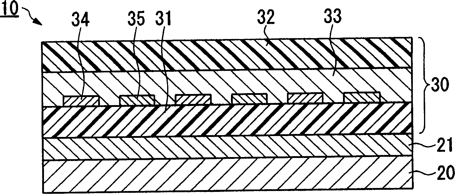
[0078] By doing the following, make Figure 4 The electrostatic chuck device with the structure shown is an electrode plate and an electrostatic chuck device.
[0079]As the insulating organic film on the upper side, a polyimide film (trade name Capton manufactured by Toray Dupont Co., Ltd.) with a film thickness of 75 μm was prepared, and it was formed on one side in the same manner as in the insulation resistance test of the insulating adhesive. electrodes and terminals. Next, the insulating adhesive 1 obtained above was coated on the electrode forming surface so that the thickness after drying was 15 μm, and then semi-cured by drying and heating to form an insulating adhesive layer. The insulating organic film on the lower side was bonded with a polyimide film (trade name Capton manufactured by Toray Dupont) having a film thickness of 50 μm. Next, the insulating adhesive layer is completely cured by heating to obtain the electrode plate for an electrostatic chuck device o...
Embodiment 2
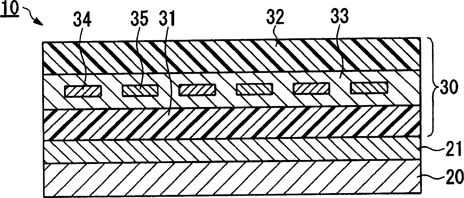
[0083] By doing the following, make figure 2 The electrostatic chuck device with the structure shown is an electrode plate and an electrostatic chuck device.
[0084] As the insulating organic film on the lower side, a polyimide film (Ube Industries, Ltd. product name Upilex) with a film thickness of 50 μm was prepared, and the insulation resistance test of the insulating adhesive was carried out on one side in the same manner. form electrodes and terminals. Next, the insulating adhesive 2 obtained above was applied on the electrode forming surface so that the thickness after drying was 20 μm, and then semi-cured by drying and heating to form an insulating adhesive layer. As the insulating organic film on the upper side, a polyethylene terephthalate film (manufactured by Teijin DuPont Film Co., Ltd.) with a film thickness of 50 μm was bonded. Next, the insulating adhesive layer is completely cured by heating to obtain the electrode plate for an electrostatic chuck device of...
Embodiment 3
[0088] By doing the following, make figure 2 The electrostatic chuck device with the structure shown is an electrode plate and an electrostatic chuck device.
[0089] As the insulating organic film on the lower side, a polyethylene terephthalate film (manufactured by Unichika Co., Ltd.) with a film thickness of 50 μm was prepared, and electrodes and terminals were formed on one surface thereof. Electrodes were formed in the same manner as in the insulation resistance test of the insulating adhesive, except that nickel with a thickness of 500 Å was subjected to aluminum plating. Next, the above-obtained insulating adhesive 1 was coated on the electrode forming surface so that the thickness after drying was 20 μm, and then semi-cured by drying and heating to form an insulating adhesive layer. The insulating organic film on the side was a polyethylene terephthalate film (manufactured by Unichika Co., Ltd.) with a film thickness of 50 μm. Next, the insulating adhesive layer is ...
PUM
| Property | Measurement | Unit |
|---|---|---|
| Thickness | aaaaa | aaaaa |
| Thickness | aaaaa | aaaaa |
Abstract
Description
Claims
Application Information