Positive pressure concentrated phase constant pressure conveying system

A conveying system and dense phase technology, applied in the field of positive pressure dense phase constant pressure conveying system, can solve problems such as inability to adjust, and achieve the effects of simple system configuration, reliable system operation, and low maintenance workload and maintenance cost.

Inactive Publication Date: 2004-09-08
杭州华源电力环境工程有限公司
View PDF0 Cites 4 Cited by
  • Summary
  • Abstract
  • Description
  • Claims
  • Application Information

AI Technical Summary

Problems solved by technology

None of these transportation forms can be dynamically adjusted as the transportation situation changes. Therefore, the output of the system, the quality of the conveyed ash, and the energy consumption are all determined at the time of design and cannot be adjusted.

Method used


Image

  • Positive pressure concentrated phase constant pressure conveying system
  • Positive pressure concentrated phase constant pressure conveying system

Examples


Embodiment Construction

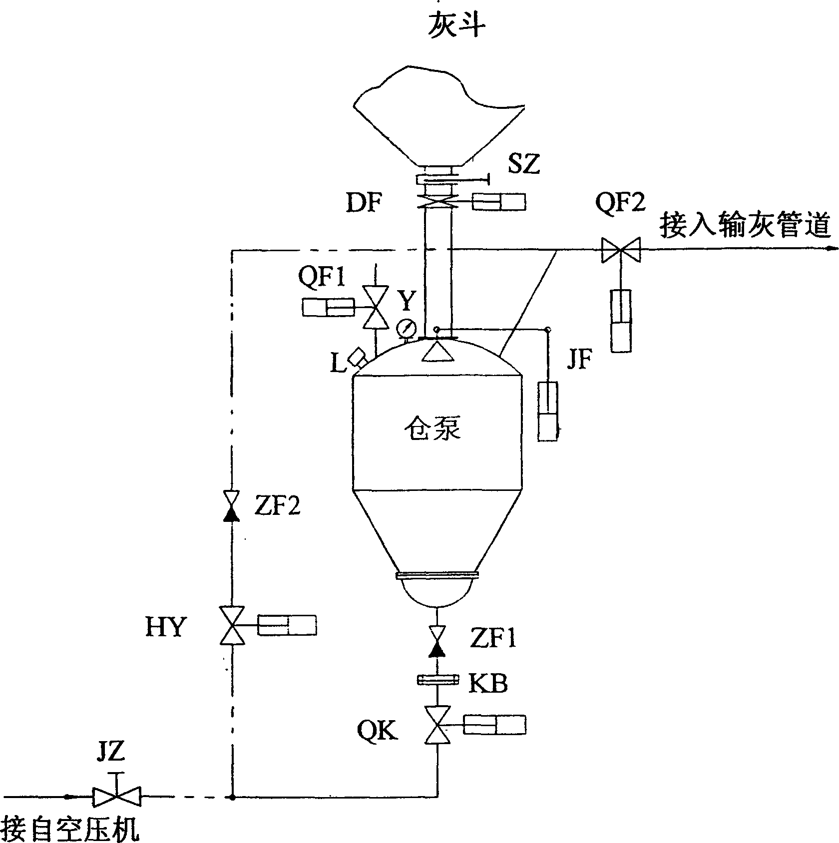
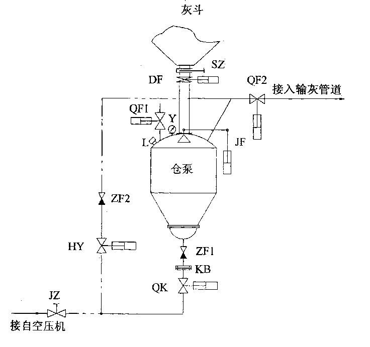
[0016] As shown in the accompanying drawings, the present invention includes a warehouse pump equipped with a material level gauge L, a pressure transmitter Y, a breathable pneumatic ball valve QF1, ash conveying pneumatic ball valve QF2, a feed valve JF, and a pneumatic butterfly valve DF on the upper part; it is connected to the lower part of the warehouse pump The air supply system; the conveying system connected with the ash conveying pneumatic ball valve QF2 of the warehouse pump.

[0017] 1) Air supply system: including air control valve QK, orifice KB, first check valve ZF1; one end of air control valve QK is connected to the air outlet end of manual shut-off valve JZ connected to the air compressor, and the air control valve QK One end is connected to one end of the orifice plate KB, one end of the first check valve ZF1 is connected to the other end of the orifice plate KB, and the other end of the first check valve ZF1 is connected to the lower part of the warehouse pu...


PUM


Abstract

The positive pressure concentrated phase constant pressure conveying system includes upper bin bump with material level gauge, pressure transducer, pneumatic ball valve, feeding valve and pneumatic butterfly valve; air feeding system comprising pneumatic control valve connected to the bin pump, orifice plate and the first non-return valve; and conveying system comprising flow regulating valve connected to the pneumatic ball valve and the second non-return valve. After the bin pump is full, air from the air compressor will be supplied to the bin pump to fluidize the material, and the orifice plate controls the air flow for constant flow rate. After the bin pump reaches set pressure, air from the air compressor forms secondary blast entering the conveying pipeline via the pneumatic ball valve. The system has one set constant conveying pressure, which is maintained via the automatic regulation of the opening of the automatic regulating valve.

Description

Technical field [0001] The invention relates to a system for conveying powder in a pipeline by air flow, in particular to a positive pressure dense phase constant pressure conveying system. Background technique [0002] Almost all fly ash produced by today's coal-fired power plants is collected in electrostatic precipitators for transport. For the transportation of fly ash, most of our country used hydraulic ash removal from the 1950s to the 1970s. After the 1980s, on the one hand, due to the increase in the boiler capacity of the unit, the amount of ash is increasing. If the ash removal system of a large power station uses a hydraulic ash removal system, it will not only increase the investment in the ash plant, but also consume a large amount of water, and will also cause secondary pollution to the environment; on the other hand, due to the continuous expansion of the country's infrastructure, the need for A large amount of dry fly ash provides a good commercial prospect ...

Claims


Application Information

Patent Timeline
IPC IPC(8): B65G53/66
Inventor 蒋文文吴剑强孔阶森马冬飞张飞明
Owner 杭州华源电力环境工程有限公司
Why Eureka
Try Eureka