Water treating magnetoelectric dialysis process

A technology of water treatment and electrodialysis, applied in the fields of magnetic field/electric field water/sewage treatment, separation method, general water supply saving, etc., to achieve the effects of improving water treatment capacity, reducing power consumption, and simple and reasonable structure

Inactive Publication Date: 2004-09-08
陈树庆 +1
View PDF1 Cites 11 Cited by
  • Summary
  • Abstract
  • Description
  • Claims
  • Application Information

AI Technical Summary

Problems solved by technology

The static magnetic field strength is preferably not less than 0.5 Tesla

Method used


Image

  • Water treating magnetoelectric dialysis process
  • Water treating magnetoelectric dialysis process
  • Water treating magnetoelectric dialysis process

Examples


Embodiment 1

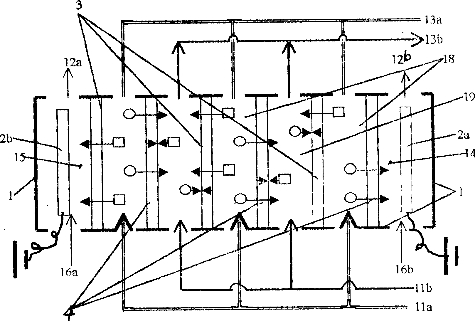
[0018] Embodiment 1. The method of the present embodiment is that it utilizes the selective permeability of the ion exchange membrane to set up a space for electrodialysis treatment water that can make the electrolyte ions in the water migrate directionally under the effect of a direct current electric field, and then treat it in the electrodialysis process. In the space of water, add a static magnetic field whose magnetic field line direction is perpendicular to the water flow direction and the current direction, so as to enhance the orientational deviation of negative and positive ions in the flowing solution. The strength of the static magnetic field is preferably not less than 0.5 Tesla.

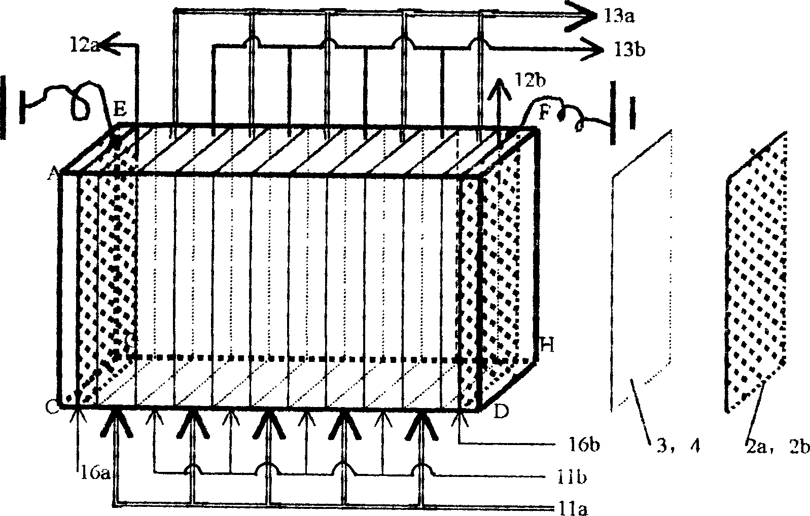
[0019] The so-called electrodialysis space can be obtained from figure 1 and figure 2 It can be seen in the structural schematic diagram and perspective view of the existing electrodialyzer in the solution that the positive and negative ions in the solution (in the figure, ←□ represent...

Embodiment 2

[0022] Embodiment 2. The difference from the method of Embodiment 1 is that the strength of the static magnetic field should not be less than 0.5 Tesla. Because the Lorent magnetic force Fm is proportional to the magnetic field strength B, the greater the magnetic field strength, the better the effect; it is more ideal if a superconductor with a strong magnetic field above 20 Tesla can be used. In addition, since the Lorent magnetic force Fm=qvB is a vector, the electrodialysis space of the magnetoelectric dialysis device of the present invention must be non-loop type, so that the liquid flow flows along the entire membrane surface, and the general direction of the flow velocity remains consistent. It can also be known from Fm=qvB that increasing the liquid flow velocity is not only conducive to improving the design offset force of the static magnetic field on the ions, but also conducive to improving the water treatment speed of the entire magnetoelectric dialysis equipment. ...

Embodiment 3

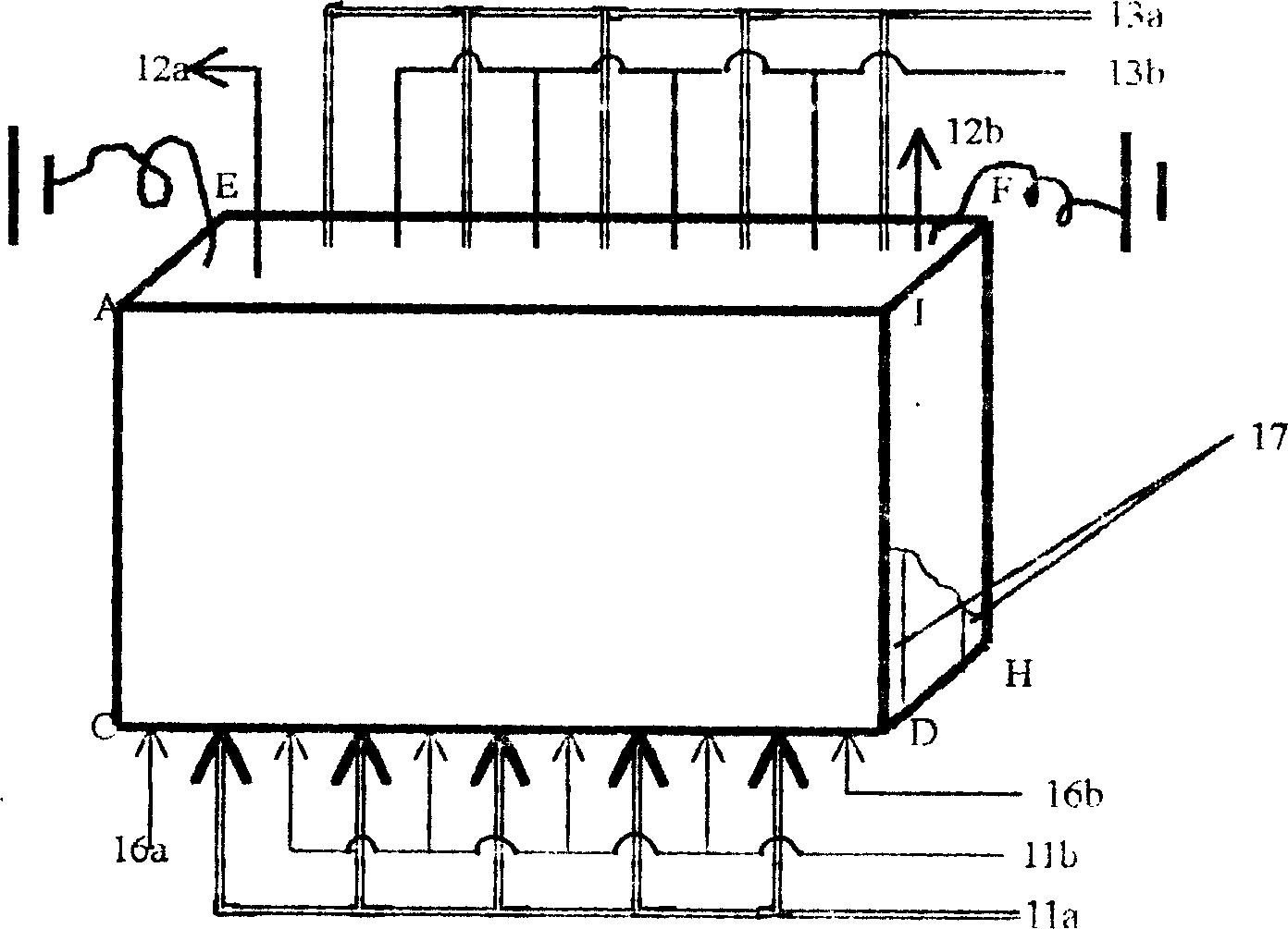
[0023] Example 3. Available from Figure 5 It can be seen from the figure that the difference between it and Embodiment 1 and Embodiment 2 is that its shell walls are material plates with different magnetic permeability, that is, the two shell walls parallel to the water flow and the current direction are high magnetic permeability materials. Plate 17, all the other shell walls are low magnetic permeability material plates with low magnetic permeability than the first two shell walls. Therefore, the reduction of the effect on the applied magnetic field due to the shielding effect of the magnetic field of the remaining shell walls is overcome.


PUM


Abstract

The water treating magnetoelectric dialysis process may be used in sea water desalting, salted water desalting, sea water concentration to produce salt, desalting industrial water, etc. Ion exchange membrane with selective penetration is utilized in establishing a water processing electric dialysis space, where electrolyte ion is made to migrate directionally in the DC electric field. The present invention features that in the electric dialysis space, one static magnetic field is applied, which has magnetic force line direction perpendicular to the water flow direction and the current direction to strengthen the directional migration of anion and cation in the flowing solution. The present invention is superior to available electric dialyser with small water processing amount, great power consumption, easy scaling and other demerits. The present invention is realized simply through applying two permanent magnets onto two opposite walls of the electric dialyser casing.

Description

[0001] This application is a divisional application. The filing date of the original application: January 10, 2002; the application number: 02101904.5; the name of the invention: the method and equipment for magnetoelectric dialysis water treatment. technical field [0002] The invention relates to a method of electrochemical water treatment. In particular, it is a method for adding a magnetic field capable of enhancing the directional deviation of charged particles in the solution to the existing electrodialysis treatment water space, and a method for magnetic treatment and descaling of water. It can be widely used in seawater desalination, brackish water desalination, seawater concentration salt production, industrial water desalination, etc. Background technique [0003] The existing electrodialysis method for water treatment by electrochemical methods uses the selective permeability of ion exchange membranes to make directional migration of electrolyte ions in water unde...

Claims


Application Information

Patent Timeline
Patent Type & Authority Applications(China)
IPC IPC(8): C02F1/469C02F1/48
CPCY02A20/124
Inventor 陈树庆张东红
Owner 陈树庆
Why Eureka
Try Eureka