High-strength welding electrode

A high-strength, electrode technology, used in welding media, welding equipment, welding/cutting media/materials, etc., can solve the problems of low yield strength of deposited metal and inability to match the high-strength performance of base metal, etc., to improve the yield strength. , good comprehensive mechanical properties, simple effect of component design

Inactive Publication Date: 2004-09-15
ADVANCED TECHNOLOGY & MATERIALS CO LTD
View PDF6 Cites 27 Cited by
  • Summary
  • Abstract
  • Description
  • Claims
  • Application Information

AI Technical Summary

Problems solved by technology

The disadvantage of this electrode is that the yield strength of the deposited

Method used


Image

  • High-strength welding electrode

Examples


Embodiment Construction

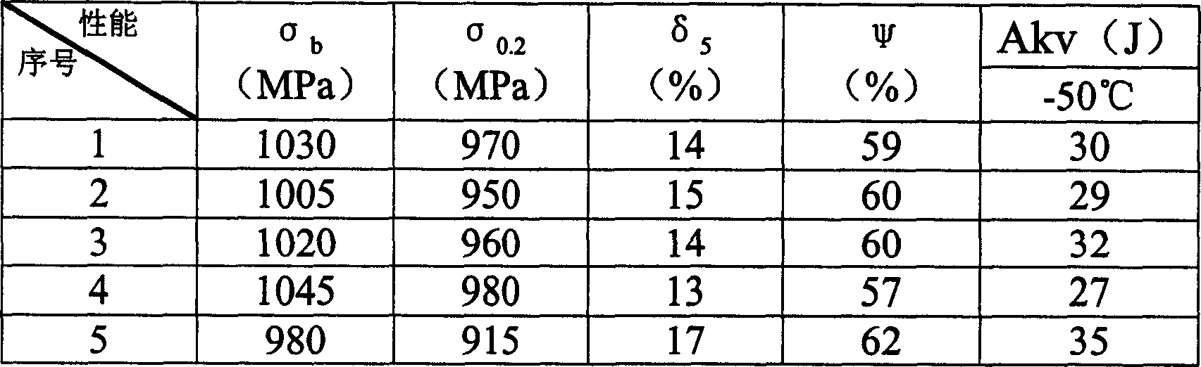
[0007] The electrode of the embodiment of the present invention obtains a deposited metal with good comprehensive mechanical properties after alloying the welding core or partially alloying the welding core and coating. According to the set composition requirements, a total of 2 heats of steel were smelted. The steel ingot was first forged into a 110mm billet, then rolled into a φ8mm wire rod, and finally drawn into an alloy welding core with a diameter of φ4mm. The forging temperature is 1180°C, and the final forging temperature is 850°C; the drawing passes are 5 passes. In order to achieve coating alloying, we selected high-quality H08E wire rod and drew it into a welding core with a diameter of φ4mm. The specific chemical composition of the welding core is listed in Table 1. The coating composition ratio of the welding rod of the embodiment is shown in Table 2; the preparation of the welding rod is to press it into a welding rod on a common oil pressure welding rod coating ...


PUM


Abstract

The invention is a high-intensity welding rod used in the welding state, able to weld high intensity structural steel whose yield strength is greater than 950MPa. The chemical components of its deposited metal: C not greater than 0.07%; Si 0.1-0.6%; Mn 1.2-1.9%; Ni 2.6-3.8%; Cr 0.41-1.50%; Mo 0.66-1.6%; Ti 0.003-0.03%; the rest Fe. Its deposited metal has good synthetical mechanical property and has tensile strength greater than 1000MPa, yield strength above 950MPa and impact work greater than 27J at -50 deg.C.

Description

[0001] Field [0002] The invention belongs to the field of welding materials. It is especially suitable for high-strength welding rods for high-strength structural steels with a yield strength greater than 950Mpa. Background technique [0003] In the field of welding materials in the prior art, there are materials that have introduced welding materials that can reach high strength: CN 1120479A; CN 1200317A; US 6114656A; US 5744782A; However, it can be seen from the article that such patents all belong to welding wire materials such as gas shielded welding and submerged arc welding. During the welding process, the deoxidizing elements titanium, silicon, manganese, etc. in the welding wire have a large burning loss. If the shielding gas is different, the degree of burning loss is also different. CO 2 The degree of burning during gas shielded welding is much higher than that of Ar gas shielded welding. The composition of the submerged arc welding wire is also different from t...

Claims


Application Information

Patent Timeline
IPC IPC(8): B23K35/32
Inventor 尹士科王移山李箕福谢少辉
Owner ADVANCED TECHNOLOGY & MATERIALS CO LTD
Why Eureka
Try Eureka