Building block type adhesive head of sheet adhesive machine

A placement head and building block technology, which is applied in the direction of assembling printed circuits, electrical components, electrical components, etc., can solve the problems of not particularly high control accuracy, complex and precise software and hardware control systems, and unfavorable application development. Achieve the effect of improving the ability to adapt to market challenges and reducing volume

Inactive Publication Date: 2004-09-29
广州市羊城科技实业有限公司
View PDF0 Cites 18 Cited by
  • Summary
  • Abstract
  • Description
  • Claims
  • Application Information

AI Technical Summary

Problems solved by technology

Therefore, the electronic assembly and placement machine is a mechatronics equipment that requires high precision, high speed, and high reliability. It belongs to a high-tech-intensive industry. Now, most of these domestic equipment are purchased from large multinational companies in the world. Not to mention the high price, the structure is not reasonable
From the perspective of the motion control of the placement head assembly and the placement spindle, the technologies at home and abroad can be mainly divided into three categories: one is the use of gear / rack transmission systems. Easy, but the problem is that it is difficult to improve the motion control accuracy of the mounting spindle, or the complexity of the mechanism must be increased in order to improve the transmission accuracy, which in turn causes the weight and volume of the mounting head assembly to increase greatly, which in turn will cause the placement The super large inertial impulse when the mounting spindle moves downward for high-speed placement, in order to ensure the placement accuracy and the service life of the machine, the size and weight of the guide rail frame that hangs the placement head assembly and drives it to translate can only be increased accordingly , resulting in a bulky and heavy machine, and a corresponding increase in cost
There is another type that is often used by large foreign high-tech companies in this regard, that is, the transmission / control system in which the servo motor under the control of digital or analog electronic equipment drives the lifting screw. This type of system uses advanced control algorithms and correspondingly accurate light , electrical and mechanical execution equipment, forming a complete control loop, high control precision, fast response, high placement efficiency, small size of the whole machine, high reliability, but the price of the whole machine under this type of technical solution is high, single It is the supporting lifting screw, which is difficult to manufacture in China, and the price of outsourcing is high. In addition, the complex and sophisticated software and hardware control system is not conducive to further application development by domestic users.
The third type is the drive control and transmission system using stepper motors and synchronous conveyor belts. This type of system is open-loop control. It is relatively simple in terms of electrical control, and the control accuracy is not particularly high. It is logically supplemented by the control correction of the optical sensor system. It should be able to meet the requirements of high-precision control, but due to the unreasonable structure of the existing placement head assembly, the space volume of the placement head assembly is too large, causing the placement head assembly to be heavy and clumsy, which also affects the whole machine. As a result, the volume of the whole machine is relatively large and the structure is complex, which limits its market promotion prospects
Moreover, due to the respective shortcomings of the above-mentioned three types of control transmission systems, it is difficult for users to flexibly and flexibly apply the software and hardware of the placement head and the placement machine on the above-mentioned placement machine according to the specific conditions of the mounted parts and products. Permanent adjustments limit the user's ability to develop the potential of the placement machine and adapt to market changes quickly and quickly

Method used


Image

  • Building block type adhesive head of sheet adhesive machine
  • Building block type adhesive head of sheet adhesive machine
  • Building block type adhesive head of sheet adhesive machine

Examples


Embodiment Construction

[0023] single head embodiment,

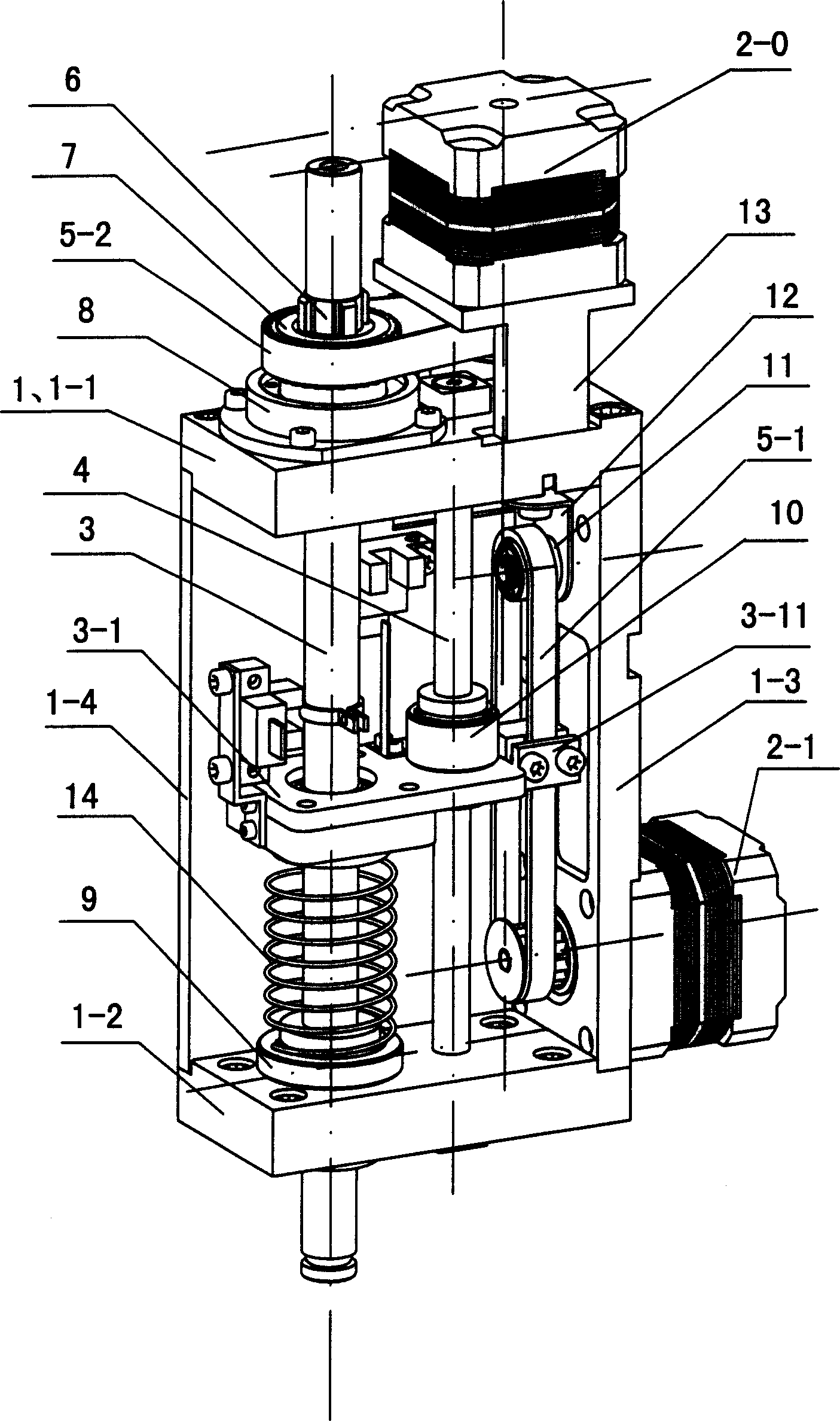
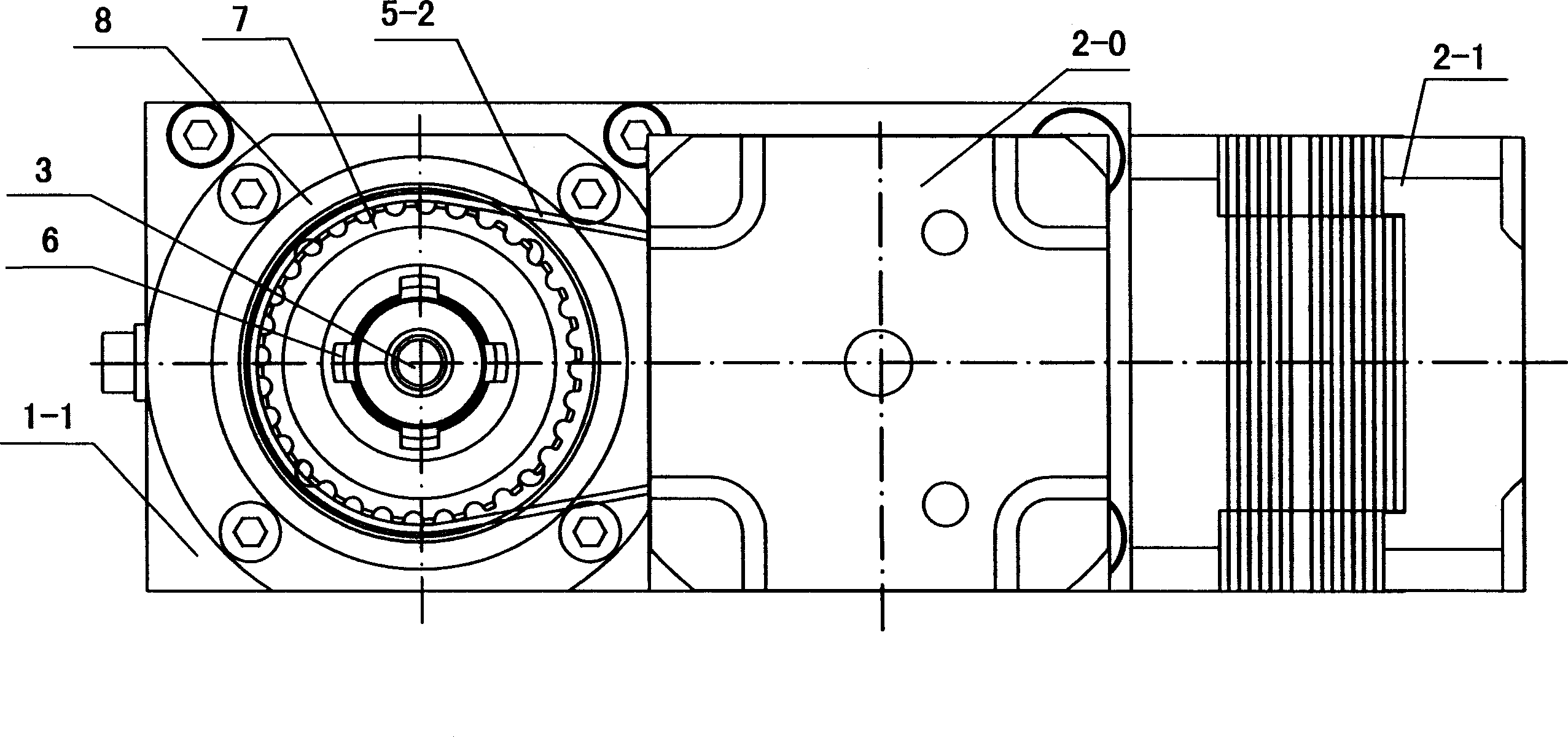
[0024] Such as figure 1 , 2 Shown: the building block mounting head of the chip mounter of the present invention, this mounting head comprises the drive motor that is contained on the frame of mounting head, transmission mechanism, mounting main shaft and suction nozzle, it is characterized in that: described paste Mounting head frame 1 is the frame of " U " shape structure that is constituted by upper shelf plate 1-1, lower shelf plate 1-2 and back plate 1-3, and described placement head frame 1 also includes from side and this U The side plates 1-4 that are connected by the frame; on the basis of the net width of the U-shaped frame 1 excluding the thickness of the side plates 1-4, the U-shaped frame has a virtual vertical bisector;

[0025] There are two drive motors, including a lift drive motor 2-1 and a rotation drive motor 2-0 that drive the mounting spindle to move accordingly, and the drive motors 2-0 and 2-1 are both stepping motors....


PUM


Abstract

A modular head of a plate overlayer includes a drive motor, drive units a main shaft and a suction port on its frame characterizing that the said head frame is composed of a top bridge plate, a bottom bridge plate and a back plate forming 'U' shape structure, the net width of the said frame has an analog vertical halving plane, an axle plane is formed between the axle line of the drive motor and the mainshalf, both of the two planes are on a same plane, the said drive units arranged adjacent to the vertical halving plane of the U frame symmetrically.

Description

【Technical field】 [0001] The invention relates to the field of placement machines for electronic assembly, in particular to the technical field of a placement machine for electronic assembly and a mounting head assembly thereof. 【Background technique】 [0002] Printed circuit boards (PCB) and integrated circuit chips are widely used spare parts in electronic information products, electromechanical products, and household appliances. The electronic parts required for mounting and welding on printed circuit boards and integrated circuit chips , Inductive components, integrated circuits, logic circuits, etc., constitute functional electronic devices that can be used practically, and the above-mentioned components that are smaller and smaller in size, different in shape, and various in shape must be mounted and welded on printed circuit boards and integrated circuit chips. The above is inseparable from the electronic assembly and placement machine. Therefore, the electronic ass...

Claims


Application Information

Patent Timeline
Patent Type & Authority Applications(China)
IPC IPC(8): H05K3/30H05K13/04
Inventor 马如震宋福民廉成李萍
Owner 广州市羊城科技实业有限公司
Why Eureka
Try Eureka