Improved high-temperature central body utilizing light reflection to reduce temperature and its manufacturing method

A center body and mirror reflection technology, applied in the direction of combustion method, sustainable transportation, high-efficiency propulsion technology, etc., can solve the problem of insufficient TBCs and achieve the effect of shortening the life of components

Inactive Publication Date: 2004-10-13
GENERAL ELECTRIC CO
View PDF2 Cites 9 Cited by
  • Summary
  • Abstract
  • Description
  • Claims
  • Application Information

AI Technical Summary

Problems solved by technology

However, even these TBCs were found to be insufficient when the combustion temperature was increased

Method used


Image

  • Improved high-temperature central body utilizing light reflection to reduce temperature and its manufacturing method
  • Improved high-temperature central body utilizing light reflection to reduce temperature and its manufacturing method
  • Improved high-temperature central body utilizing light reflection to reduce temperature and its manufacturing method

Examples


Embodiment Construction

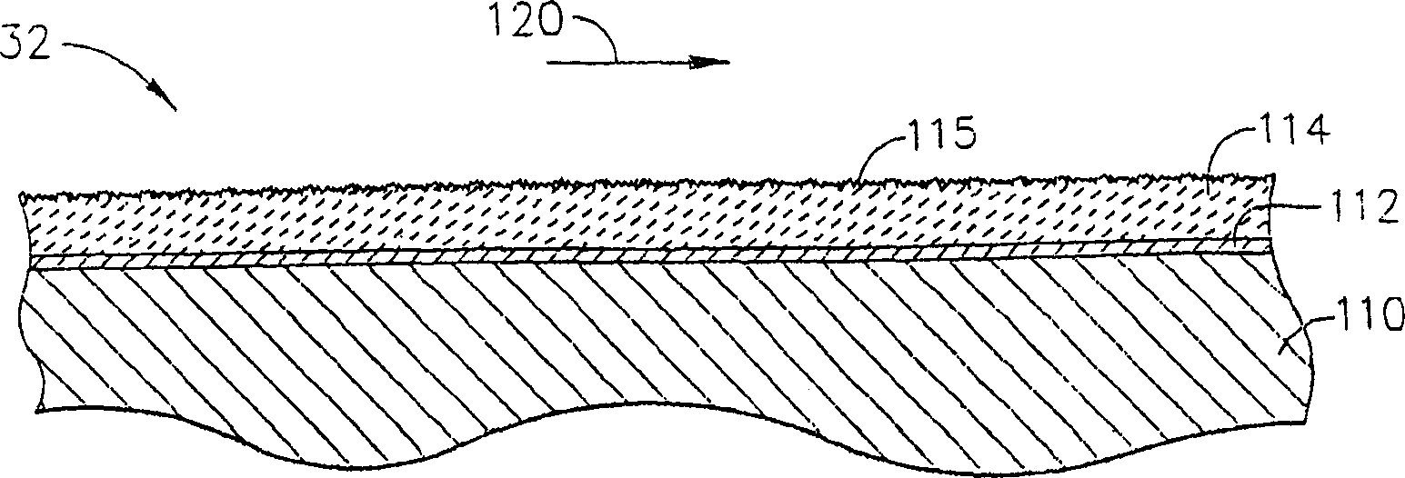
[0019] According to the present invention, a hot section member of a gas turbine constituting a gas flow path or disposed in the gas flow path is applied with a specular light reflection thin layer material having high temperature properties. The applied material has a smooth surface finish that mirrors thermal energy back into the fluid channels and away from other thermal section components.

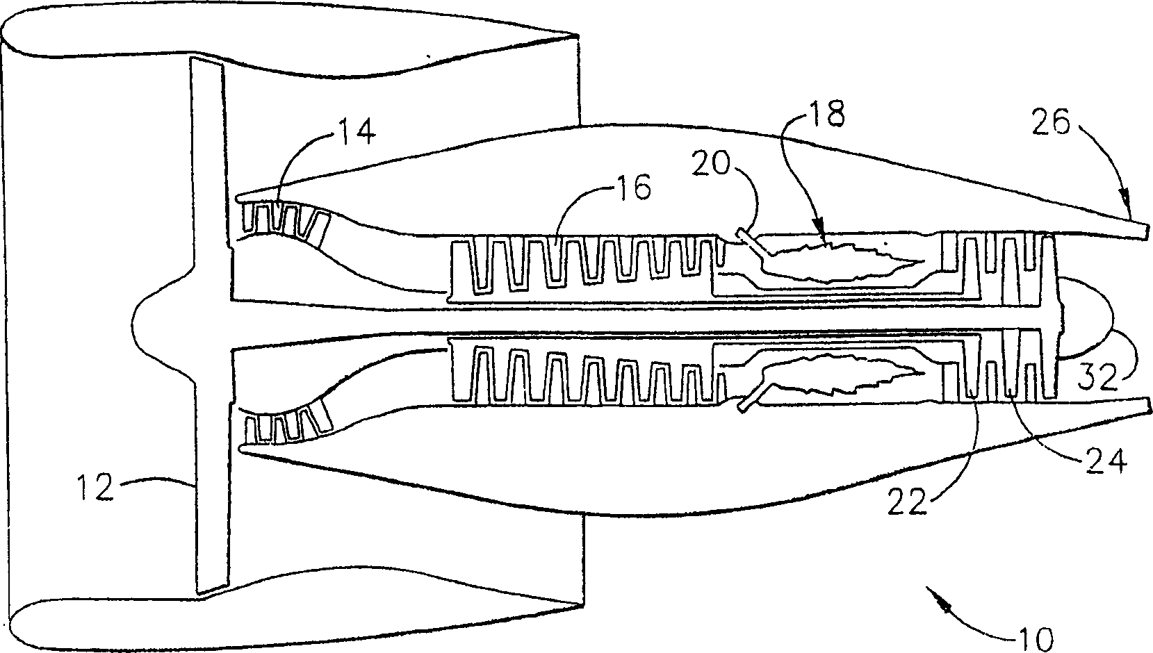
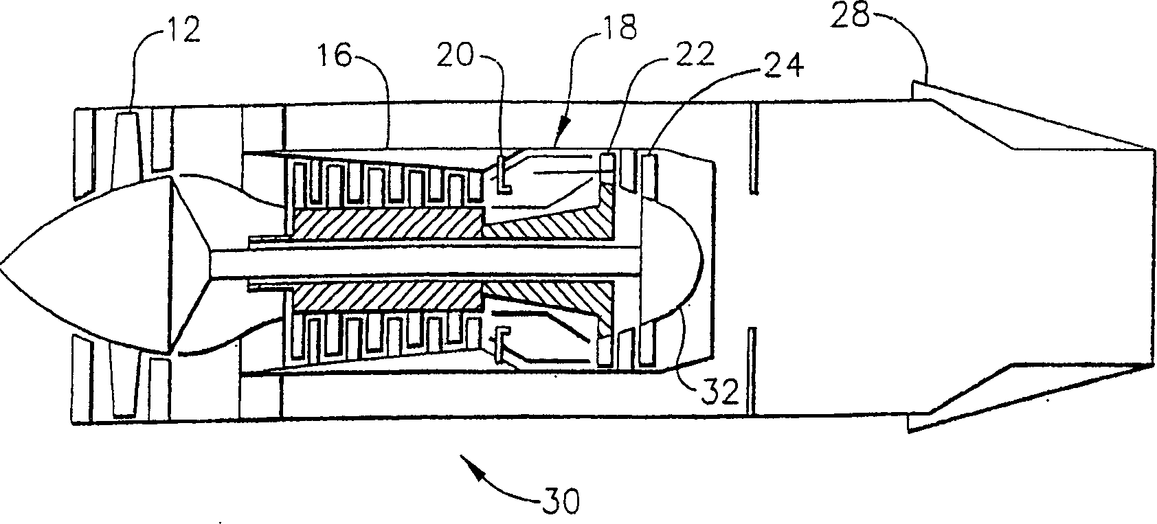
[0020] figure 1 is a schematic diagram of a high bypass ratio aircraft gas turbine 10 . During operation, air is forced through the fan 12 . A portion of the air bypasses the center of the engine and creates the thrust that propels the engine. A portion of the air is compressed to 10-25 times atmospheric pressure in the engine's supercharger 14 and compressor 16 sections, and is adiabatically heated to 800-1250°F (430-680°C) in the process. This heated and compressed air enters the combustion chamber portion 18 of the engine and mixes with fuel supplied via a fuel nozzle system 20 ....


PUM

PropertyMeasurementUnit
surface roughnessaaaaaaaaaa
surface smoothnessaaaaaaaaaa
surface roughnessaaaaaaaaaa

Abstract

A high temperature gas turbine component (32) for use in the gas flow path (120) that also is a specular optical reflector. A thin layer of a high temperature reflector is applied to the gas flow path of the component, that is, the surface of the component that forms a boundary for hot combustion gases. The component typically includes a thermal barrier coating (114) overlying the high temperature metallic component that permits the component to operate at elevated temperatures. The thermal barrier coating (114) must be polished in order to provide a surface that can suitably reflect the radiation into the gas flow path (120). A thin layer of the high temperature reflector (116) the is applied over the polished thermal barrier coating (114) by a process that can adequately adhere the reflector (116) to the polished surface without increasing the roughness of the surface. The high temperature reflector (116) can be applied to any surface aft of the compressor, such as on a centerbody (32). The surface reflects radiation back into the hot gas flow path (120) or into the atmosphere. The reflected radiation is not focused onto any other hardware component. The design of the component is such that the radiation is returned to the gas flow path (120) or sent to the atmosphere rather than absorbed into a component wall that only serves to increase the temperature of the wall.

Description

[0001] 【Related application】 [0002] This application relates to the application 10 / 335657 entitled "IMPROVED HIGHTEMPERATURE SPLASH PLATE FOR TEMPERATURE REDUCTION BY OPTICALREFLECTION AND PROCESS FOR MANUFACTURING" with the agency file number 13DV-13956 and the application 10 / 335657 with the agency file number 13DV-13957 entitled "IMPROVED HIGH TEMPERATURE TEMPERATURECER REDUCTION BY OPTICAL REFLECTION ANDPROCESS FOR MANUFACTURING" APPLICATION 10 / 335647 AND APPLICATION 10 / 335647 AND APPLICATION 10 / 33959 ENTITLED "IMPROVED HIGH TEMPERATURE COMBUSTOR WALL FORTEMPERATURE REDUCTION BY OPTICAL REFLECTION AND PROCESS FORMANUFACTURING" 45 AND PROCESS FORMANUFACTURING 3 / 42 Applications filed concurrently on December 31, 2002 and both are assigned to the assignee of the present invention, which are incorporated herein by reference. 【Technical field】 [0003] This invention relates to gas turbine engines and, more particularly, to improvements in components of such engines to reduce ...

Claims


Application Information

Patent Timeline
Patent Type & Authority Applications(China)
IPC IPC(8): F01D25/00C23C30/00F01D5/28F02C7/00
CPCF05C2253/12F05D2300/611F05D2300/133F05C2203/0886F23M2900/05004Y02T50/673Y02T50/67F05C2201/0412F05C2201/0427Y02T50/672F05D2300/143F01D5/288F05D2230/90F05C2251/06F05D2300/211F05D2300/504F23R3/002Y02T50/60
Inventor J·F·阿克尔曼P·V·阿斯兹曼B·A·纳加拉C·D·杨N·B·朱斯蒂斯
Owner GENERAL ELECTRIC CO
Why Eureka
Try Eureka