
Optical transmission system with automatic optimizing transmitting end performance and automatic optimizing method

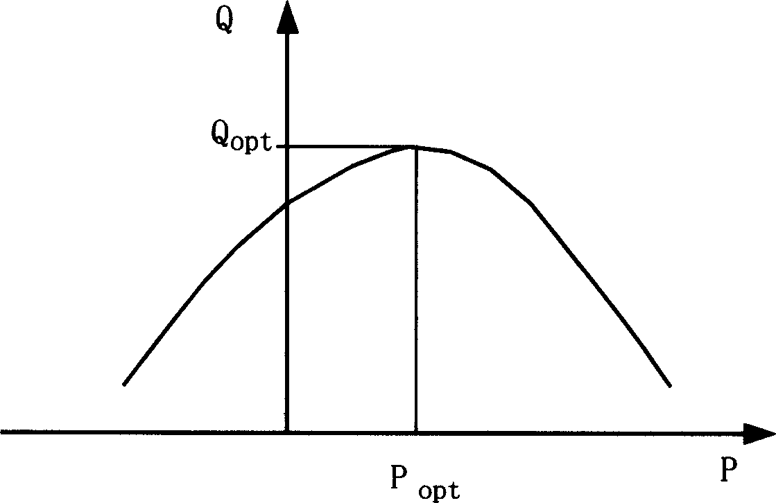
An automatic optimization, transmitter technology, applied in transmission systems, electromagnetic wave transmission systems, electromagnetic transmitters, etc., can solve problems such as damage to practicability, long test time, and long system optimization and adjustment time, and achieve the effect of system performance optimization.

Inactive Publication Date: 2004-11-10
ZTE CORP
View PDF5 Cites 2 Cited by
  • Summary
  • Abstract
  • Description
  • Claims
  • Application Information

AI Technical Summary

Problems solved by technology

In our opinion, there is no need to test the optical signal-to-noise ratio when realizing system optimization; while testing the bit error rate will cause the system optimization and adjustment time to be too long due to the long test time, which will damage the practicability of the invention, especially in the bit error rate. When the rate is low

Method used


Image

  • Optical transmission system with automatic optimizing transmitting end performance and automatic optimizing method
  • Optical transmission system with automatic optimizing transmitting end performance and automatic optimizing method
  • Optical transmission system with automatic optimizing transmitting end performance and automatic optimizing method

Examples


Embodiment Construction

[0033] The specific implementation manners of the present invention will be further described in detail below in conjunction with the accompanying drawings. The marks in the figure represent respectively: 1: input signal

[0034] 2: Transmission line

[0035] 3: Device monitoring route (connected between the transmitter and receiver)

[0036] 4: Transmitter combiner

[0037] 5: Receiver splitter

[0038] 10: Transmitter output optical interface

[0039] 11: Continuous wave laser source

[0040] 12: Intensity modulator

[0041] 13: Phase modulator

[0042] 14: Driving circuit 1, which is the driving circuit of the intensity modulator

[0043] 15: Drive circuit 2, which is the drive circuit of the phase modulator

[0044] 16: Output optocoupler

[0045] 17: Laser automatic power control circuit

[0046] 18: CPU system that controls the transmitter

[0047] 19: Transmitter routing forwarder

[0048] 20: Transmitter general controller

[0049] 21: Transmitter multi-ch...


PUM


Abstract

The invention discloses an optical transmission system automatically optimizing transmit end in optical communication field and its automatic optimizing method. It includes transmit end and receive end as well as transmission line and monitoring channel route; where the transmit end includes: continuous wave light source, forced modulator, phase modulator, strength modulation driving circuit, phase modulation driving circuit, sampling optical coupler, automatic power control circuit, CPU system, transmit-end route transmitter, and output optical interface; the receive end includes: input optical interface, input optical coupler, receiver, Q-value tester, control CPU, and receive-end route transmitter. It can automatically implement system performance optimization without a large quantity of manual debugging, meeting operating and maintenance requirements of on-line equipment. It is applied to a system with signal FEC coding and also without signal FEC coding.

Description

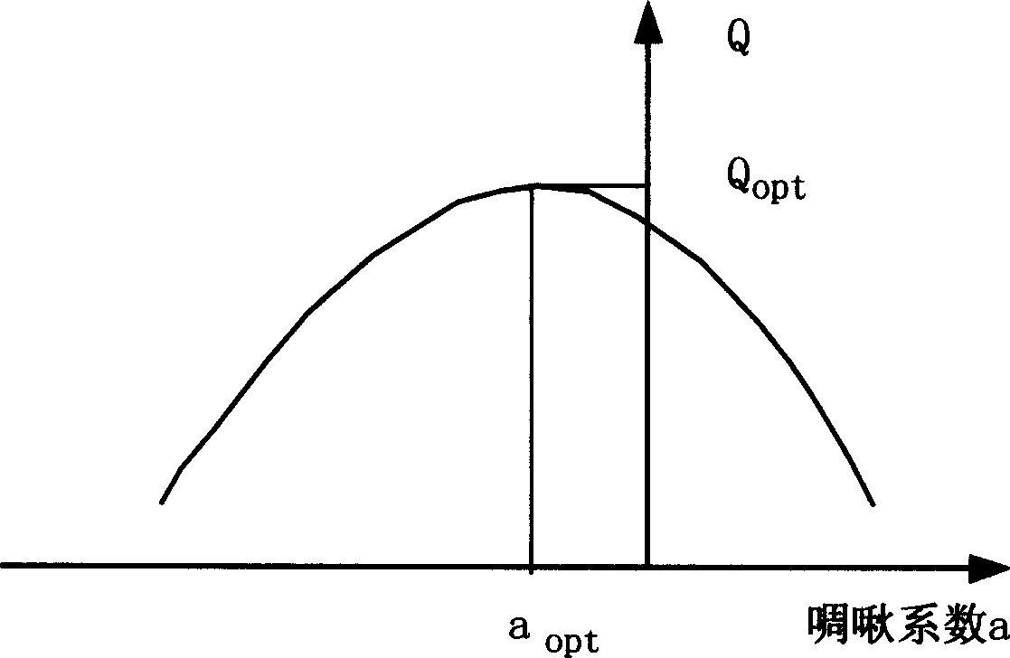
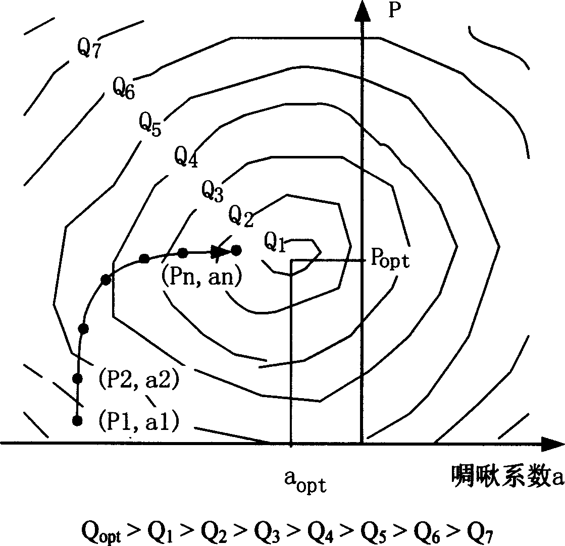
technical field [0001] The present invention relates to transmission equipment in the field of optical communication, in particular to a laser modulation transmission and receiving system, a device for automatically adjusting the transmitting end in order to realize automatic optimization of the system, and an automatic control method adopted. Background technique [0002] The characteristics of the light source in the optical transmission system have an impact on the system performance. After the light source is modulated by intensity, the main characteristics are average power and chirp. The average power reflects the intensity of the optical signal output, and the chirp is the phase change characteristic added to the intensity modulation signal, which reflects the dynamic change of the carrier. With other conditions unchanged, the influence of the average power input into the transmission line on the performance of the transmission system is: when the average power is low...

Claims


Application Information

Patent Timeline
IPC IPC(8): H04B10/54H04B10/548
Inventor 王加莹
Owner ZTE CORP
Learn More