
Method for manufacturing lens

A lens and correction lens technology, applied in manufacturing tools, glass pressing, glass manufacturing equipment, etc., can solve the problems of poor surface accuracy, reduced productivity, and increased cost of glass lenses, and achieve significant improvement in surface accuracy and difficulty in shape forming. Large, fine surface finish

Inactive Publication Date: 2004-12-01
HOYA CORP
View PDF3 Cites 8 Cited by
  • Summary
  • Abstract
  • Description
  • Claims
  • Application Information

AI Technical Summary

Problems solved by technology

[0009] However, in the case of press forming a concave meniscus lens, if the pressure is only applied again during the cooling process as in Patent Document 1, a lens with good surface precision cannot be obtained in many cases.
In addition, when the forming die is processed under the condition of forming distortion, it is undesirable to process the forming die into a shape that cancels the distortion, resulting in increased man-hours, increased cost, and reduced productivity.
[0010] The deterioration of the surface accuracy of the glass lens when the precision press forming method is used is caused by deformation during cooling after press working, which is also known in the above-mentioned prior art
However, in the case of concave meniscus lenses, it is not known at all how to control the deformation of the glass from press forming to mold release in order to press form a lens with good surface accuracy.
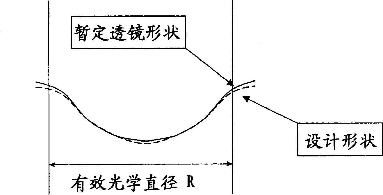
For example, if figure 1 As shown in , the radius of curvature of the formed lens (tentative lens shape) may change in the radial direction relative to the design value (design shape) of the lens, resulting in distortion, so that the desired surface accuracy cannot be obtained
To sum up, it is impossible to obtain a concave meniscus lens with good surface precision only with the solutions of the prior art

Method used


Image

  • Method for manufacturing lens
  • Method for manufacturing lens
  • Method for manufacturing lens

Examples


Embodiment 1

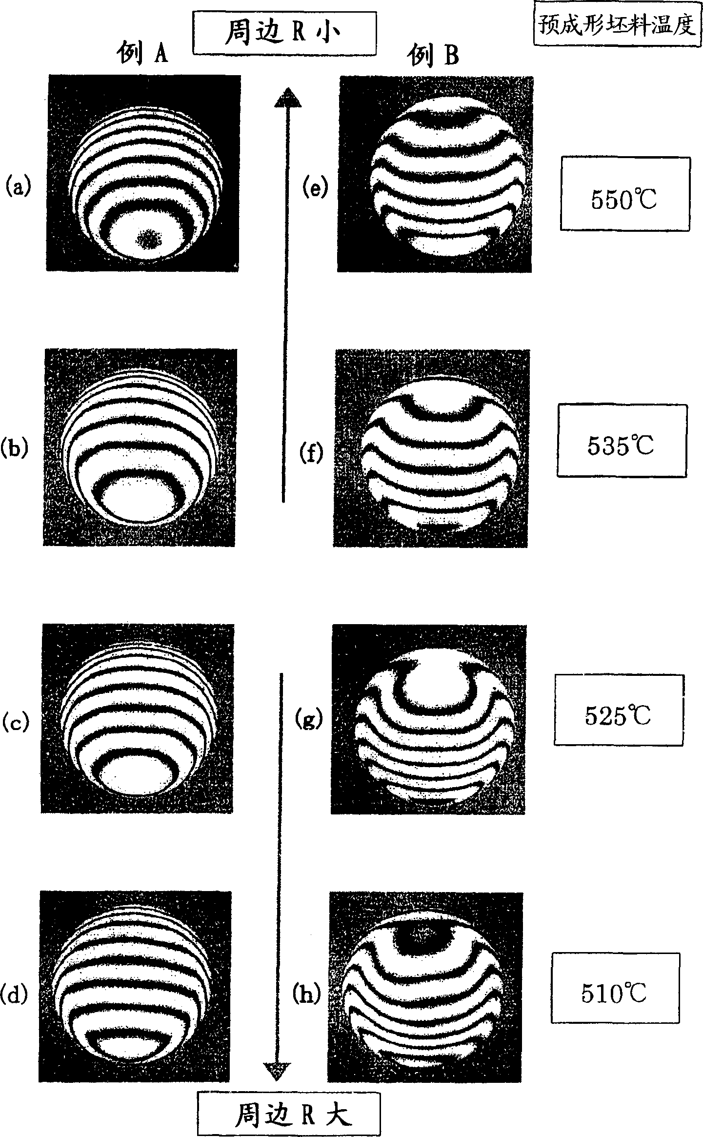
[0154] [Example 1] (Change in distortion caused by glass raw material temperature)

[0155] A concave meniscus lens with a diameter of 11 mm and a central plate thickness of 1.2 mm was molded, and the first surface and the second surface were spherical. Preform phosphate glass feedstock (Tg: 450Ts: 490°C) into a diameter of 10mm and a volume of 420mm 3 The flat spherical shape is used as the preform blank. Bring it to a viscosity of 10 7 ~10 9 After heating at various temperatures (550-510°C) of dPaS, it is provided to heat until the glass viscosity is equivalent to 10 9 The temperature of dPaS (510°C) and the equivalent of 10 according to the glass viscosity 10 Immediately raise the lower die between the upper and lower dies at dPaS temperature (490°C) to press the preform between the upper and lower dies with an initial pressure of 150kg / cm 2 , Cooling begins after the pressure processing starts (the cooling speed of the upper and lower molds is 100°C / min). The lower m...

Embodiment 2

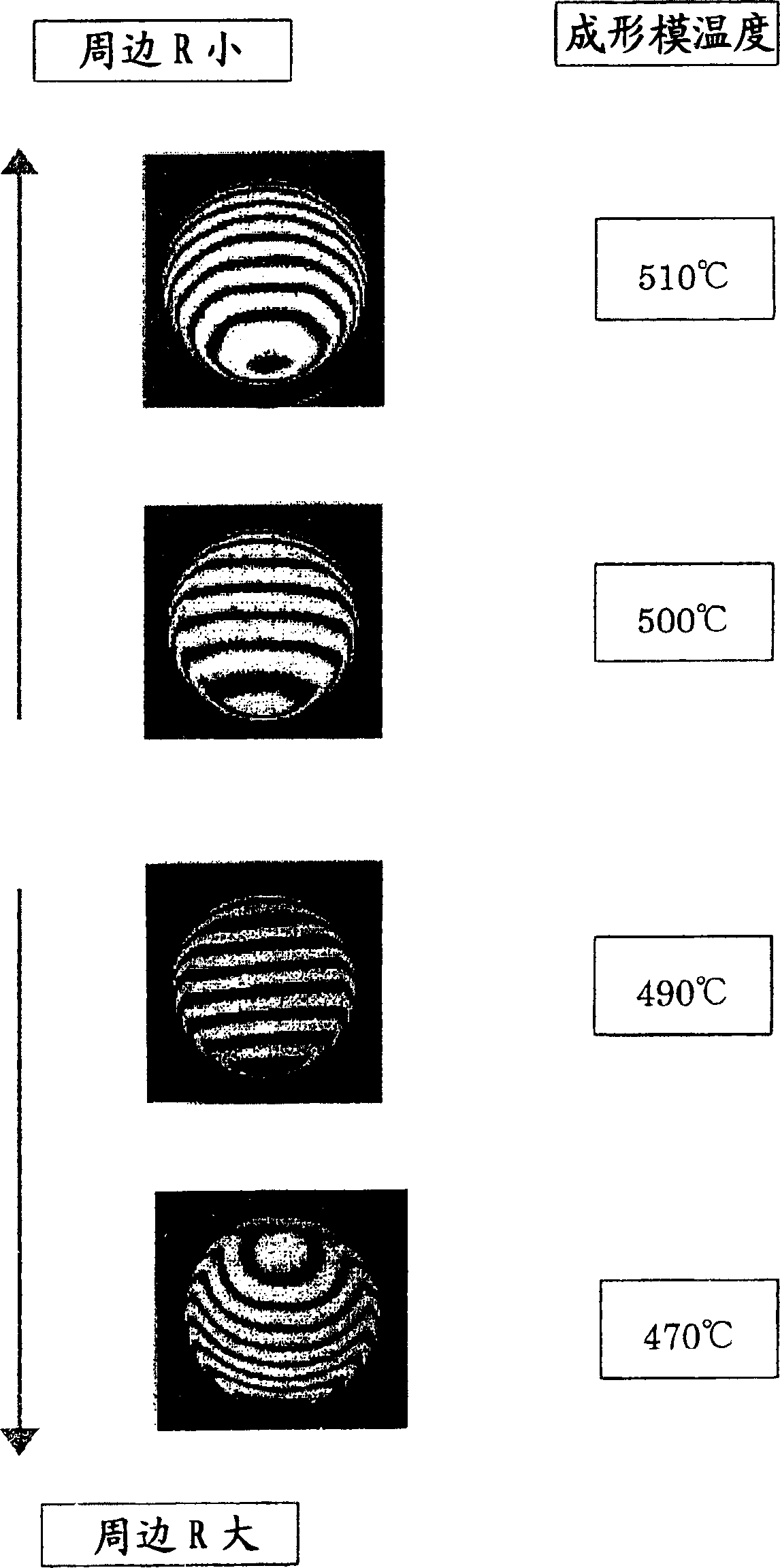
[0158] [Example 2] (Change in distortion caused by mold temperature)

[0159] Using the same preform and forming die as in Example 1, the preform is equivalent to 10 according to the glass viscosity. 7 After heating at the temperature of dPaS (550°C), it is heated to a glass viscosity of 10 9 ~10 11 The lower mold at a temperature of dPaS (470-510° C.) raises the lower mold immediately, and press-works the preform between the upper and lower molds. Press working pressure, press working procedure are identical with embodiment 1. In addition, the temperature of the upper and lower molds was set to be the same, the cooling rate of both the upper and lower molds was 100°C / min, and the second pressurization was 460°C. Such as image 3 As shown, when the mold temperature is high, the surface shape is such that the radius of curvature of the peripheral part is smaller than that of the central part. On the contrary, as the temperature decreases, the radius of curvature of the peri...

Embodiment 3

[0160] [Example 3] (Change in distortion caused by temperature difference between upper and lower dies and cooling rate difference)

[0161] Using the same preform and forming die as in Example 1, the preform is equivalent to 10 according to the glass viscosity. 7 After heating at the temperature of dPaS (550°C), it is heated to a glass viscosity of 10 9 ~10 11 The lower mold (mold for forming the first surface) at a temperature of dPaS (490 to 505°C) immediately raises the lower mold, and the preform Formed blanks are press-worked. The pressure processing procedure is the same as that of Example 1, but the cooling rate after the pressure processing is changed to 80°C / min for the upper die and 75-105°C / min for the lower die.

[0162] Such as Figure 4 As shown, there is such a tendency that if the temperature of the lower mold at the start of press working is relatively lower than that of the upper mold, the surface shape is such that the radius of curvature of the periphe...


PUM


Abstract

Method of manufacturing a concave meniscus lens with good surface precision. The method of manufacturing a concave meniscus lens method comprises press molding a glass material in a heat-softened state with a pressing mold. The heated glass material is fed between the molding surfaces of the preheated upper and lower pressing molds and press molded, and the upper and lower pressing molds are cooled to obtain a temporary lens; and when an irregularity is produced on one of the surfaces of the temporary lens, the temperature of the glass material, the preheating temperature of the upper and / or lower molds, or the cooling rate of the upper and / or lower molds is corrected to obtain a corrected lens. When the press molding of the temporary lens is conducted by the first and second pressure applications and an irregularity is produced on one of the surfaces of the temporary lens, the load of the second pressure application is corrected to obtain a corrected lens. The correction is repeated until the irregularity of the corrected lens obtained falls within the permitted range.

Description

technical field [0001] The present invention relates to a manufacturing method of precision press processing for obtaining high-precision glass optical elements without subsequent processing such as grinding and polishing, and is particularly suitable for forming a meniscus lens. Background technique [0002] In the field of precision pressure processing to which the present invention belongs, the glass raw material in a heated and softened state is pressure-formed by using a forming mold that is precisely mirror-processed into a predetermined shape, and the molding surface of the mold is transferred to the glass raw material, thereby forming a product with a predetermined shape. Optical components with surface precision. However, in the glass raw material to which the shape of the forming surface is transferred by press forming, in the subsequent cooling process until demoulding, due to volume shrinkage, physical force received during pressurization, and remaining due to co...

Claims


Application Information

Patent Timeline
Patent Type & Authority Applications(China)
IPC IPC(8): C03B11/12C03B11/16
CPCC03B2215/48C03B11/122C03B11/16C03B2215/69C03B11/125
Inventor 坂井裕之广田慎一郎
Owner HOYA CORP
Learn More