Travelling time difference based power distribution network fault positioning method and apparatus

A technology for fault location and transmission network, applied in the direction of fault location, information technology support system, etc., can solve problems such as unsatisfactory operation of fault location devices, unfavorable power system safe operation, and low fault location accuracy, so as to improve anti-interference ability, The effect of simplifying the structure and improving the positioning accuracy

Active Publication Date: 2004-12-08
湖南湘能电气自动化有限公司
View PDF2 Cites 21 Cited by
  • Summary
  • Abstract
  • Description
  • Claims
  • Application Information

AI Technical Summary

Problems solved by technology

The fault location accuracy of this method is low, and it is greatly affected by factors such as changes in system operating parameters, including: (1) the influence of the transmission characteristics of voltage and current transformers; (2) the influence of line parameters and system parameter setting errors (3) The influence of line parameters with changes in climate, operating years, pollution degree and other factors; (4) The influence of fault transient harmonics
Conventional fault location devices, usually based on fault steady-state quantities, do not work well in the field
Application No. 02115506.2 titled "Transmission Line Fault Point Locating Method and Device" discloses a method of extracting traveling wave signals for fault location by using small reactances connected in series with capacitive elements in substations; the above two methods require Changing the wiring of high-voltage equipment in the system is not conducive to the safe operation of the power system, and it is difficult to promote in my country's power system
Application No.: 00131128.X titled: "Power Line Protection Method and Traveling Wave Sensor for the Method", which discloses a CVT ground wire with a line wave sensor, which records the arrival time of the fault traveling wave. The method of fault location, the system is complicated, and only CVT is selected as the installation point, which is subject to certain limitations

Method used


Image

  • Travelling time difference based power distribution network fault positioning method and apparatus
  • Travelling time difference based power distribution network fault positioning method and apparatus
  • Travelling time difference based power distribution network fault positioning method and apparatus

Examples


Embodiment Construction

[0034] The present invention will be further described in detail below in conjunction with the accompanying drawings and specific embodiments.

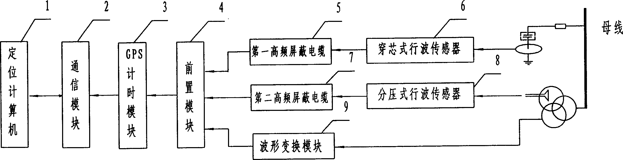
[0035] The structure of the present invention is as figure 1 As shown, it consists of a positioning computer 1, a communication module 2, a GPS timing module 3, a front module 4, a first high-frequency shielded cable 5, a core-through traveling wave sensor 6, a second high-frequency shielded cable 7, and a voltage-dividing line Wave sensor 8, waveform transformation module 9 and other components. 1 core-through traveling wave sensor connected to the grounding wire of capacitive equipment (capacitive current transformer CT end screen, transformer bushing end screen, wall bushing end screen, etc.) Transformed into a signal below 10-500V, it is sent to the input terminal of the front module 4 through the first high-frequency shielded cable 5; at the same time, the voltage-dividing traveling wave sensor 8 connected to the open triangle w...


PUM


Abstract

In the method, feed-through line transducer is socket-connected on earth line of any capacity equipment in electric station of electric net or parlle-connected voltage division line transducer on inductor to obtain electric net abrupt signal, occuring accurate time of each abrupt signal is recorded and arrival time of abrupt signal recorded by station is collected by computer, accurate position of fault point and actual length of nonfault line is calculated by positioning computer, bus three phase voltage waveform is converted to be square wave sent to presetmodule by waveform conversion module for carrying on phase angle measurement of electric net.

Description

technical field [0001] The invention relates to the field of power system protection and the field of high-voltage testing technology, in particular to a transmission network fault location method and device based on traveling wave time difference. Background technique [0002] The precise positioning of the fault point of the transmission network has not been solved for a long time, which directly affects the power supply recovery time of the fault line and also brings a heavy burden to the line operation and maintenance personnel. Existing fault location methods include: a conventional fault location method using fault steady-state quantities, and a fault traveling wave location method using fault transient traveling waves. [0003] The fault location method based on fault steady-state quantities installs current transformers and capacitive voltage transformers at both ends of the power line to detect current and voltage steady-state quantities, use...

Claims


Application Information

Patent Timeline
Patent Type & Authority Applications(China)
IPC IPC(8): G01R31/08
CPCY04S10/522Y04S10/52
Inventor 曾祥君周延龄林干
Owner 湖南湘能电气自动化有限公司
Why Eureka
Try Eureka