Portable ultra thin passive analogue electron circuit experiment box

An analog electronic and portable technology, applied in the field of teaching instruments, can solve the problems of no electromagnetic shielding effect, multiple laboratory spaces, poor waveform quality, etc., to facilitate preview or design experiments, improve experimental quality, and good electromagnetic compatibility Effect

Inactive Publication Date: 2004-12-22
JILIN UNIV
View PDF0 Cites 8 Cited by
  • Summary
  • Abstract
  • Description
  • Claims
  • Application Information

AI Technical Summary

Problems solved by technology

[0003] However, there are many defects in this experimental box in actual use
It has not been fundamentally improved for a long time, and the structure of the simulation experiment boxes provided by various manufacturers is basically the same, which is difficult to meet the current higher quality teaching needs
Its main problem is: the box body of existing analog electronic circuit experiment box is too big, occupies too much laboratory space, is not easy to carry simultaneously; The performance indicators are quite different, the humming sound is serious, the output voltag

Method used


Image

  • Portable ultra thin passive analogue electron circuit experiment box
  • Portable ultra thin passive analogue electron circuit experiment box
  • Portable ultra thin passive analogue electron circuit experiment box

Examples


Embodiment 1

[0014] Embodiment 1 further illustrates the structure of the present invention in conjunction with accompanying drawing

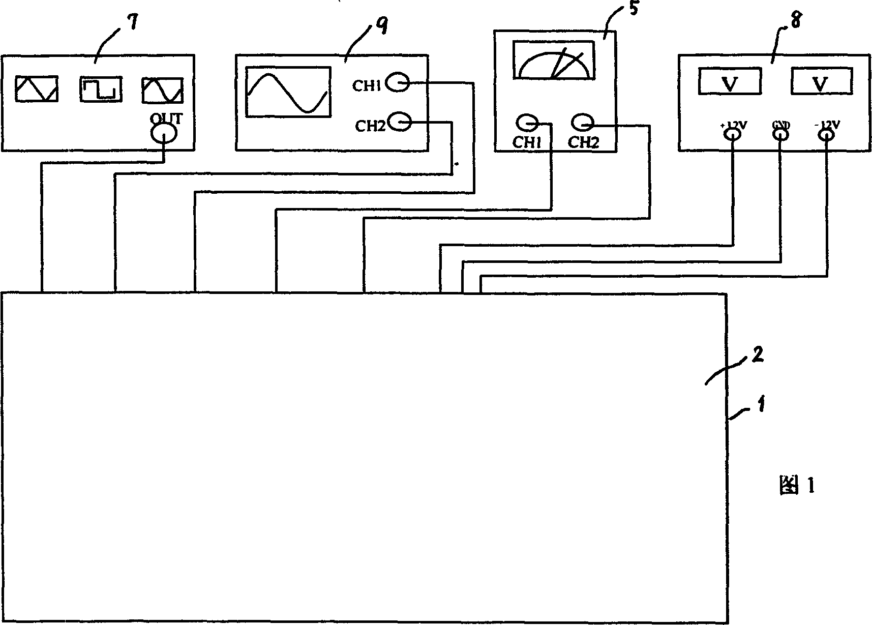
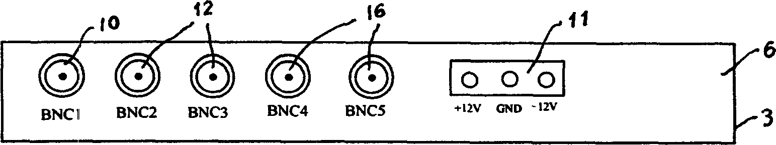
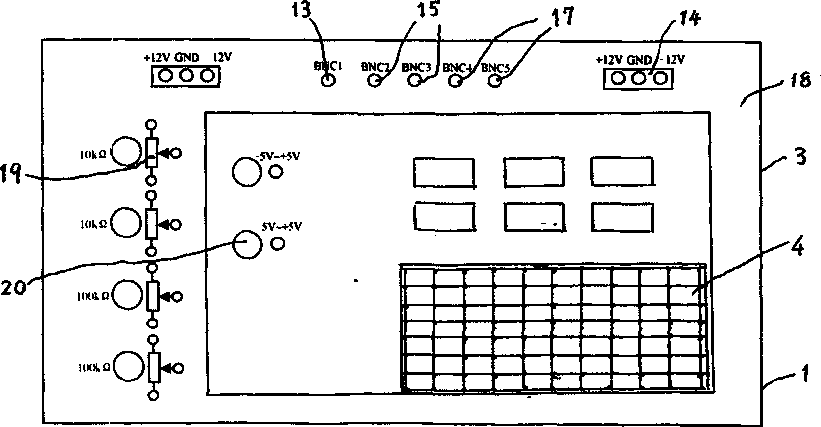
[0015] The structure of the portable ultra-thin passive analog electronic circuit experiment box of the present invention comprises: box body 1, is made up of upper cover 2 and box bottom 3 two parts, and it is lined with shielding metal layer; There is the breadboard 4 of matrix jack; Test jack. Box bottom side rear panel 6 is equipped with oscilloscope wiring bayonet 12, function signal generator wiring bayonet 10, power supply wiring bayonet 11 and AC millivoltmeter wiring bayonet 16, and they are respectively connected with the oscilloscope wiring jack on the front panel 18 at the bottom of the box. 15. Function signal generator wiring jack 13, power supply wiring jack 14 and AC millivolt meter wiring jack 17 are electrically connected; said upper cover 2 is connected with the front and bottom surfaces of box bottom 3 with the same self-locking device r...

Embodiment 2

[0021] Embodiment 2 The experimental box can provide two sets of continuous and precise adjustable -5V~+5V DC signal sources.

[0022] The DC signal source is arranged inside the box body 1, and its structure is a voltage stabilizing circuit with an isolation stage. Precise adjustment is realized with a precision multi-turn potentiometer.

[0023] In the experiment box, except for the ±12V regulated power supply, all circuits, signal sources and the "ground" terminals of the BNC interface are connected together internally.

Embodiment 3

[0024] Embodiment 3 relates to the shielding metal layer in the box.

[0025] Copper mesh with relatively dense mesh can be used as the shielding metal layer; the upper cover 2 and the bottom 3 of the box body 1 can also be directly made by using reticulated foamed nickel-copper and hard plastic composite plates.


PUM


Abstract

The invention relates to a portable ultrathin passive analog electronic circuit test box, including a box body lined with a screening metallic layer, a bread board and many test jacks; the box bottom-side back panel is installed with an oscillograph wiring bayonet, a functional signal generator wiring bayonet, a power supply wiring bayonet and an AC millivoltmeter wiring bayonet, connected with an oscillograph wiring jack, a functional signal generator wiring jack, a power supply wiring jack and an AC millivoltmeter wiring jack on the box bottom-side front panel, respectively; the right and bottom surfaces of the top cover and the box bottom of the box body are connected with the same self-locking device, respectively; the box bottom-side back panel has the box body holding a potentiometer and a DC signal source of -5V-+5V. It can achieve an ideal experimental effect; it is convenient for the students to prepare or design experiment after class and convenient to store and transport; it has good EMC.

Description

technical field [0001] The ultra-thin passive analog electronic circuit experiment box of the invention belongs to the field of teaching instruments, and is an upgraded replacement product of the common analog electronic circuit experiment box commonly used in current colleges and universities. Background technique [0002] The prior art similar to the present invention is an analog electronic circuit experiment box. The basic structure is to use aluminum profiles or ABS plastics to make a box. The box is equipped with a simple DC power supply and a simple function signal generator. Copper-clad plates are used in the box. In the experimental area of ​​the manufactured unit circuit, each experimental unit in the experimental area is equipped with an appropriate amount of test jacks. This kind of experimental box is equipped with an oscilloscope and a digital multimeter outside to complete the experimental items specified by the experimental box. [0003] However, there are m...

Claims


Application Information

Patent Timeline
IPC IPC(8): G09B23/18
Inventor 田小建单江东王剑钢郭树旭
Owner JILIN UNIV
Why Eureka
Try Eureka