
Method and device for monitoring fault of motor vehicle brake system

A brake system and monitoring device technology, which is applied in the direction of brake safety systems, etc., can solve problems such as hydraulic oil inlet and hydraulic oil passages, brake mechanisms with mechanical failures, etc.

Inactive Publication Date: 2004-12-29
王元虎
View PDF0 Cites 9 Cited by
  • Summary
  • Abstract
  • Description
  • Claims
  • Application Information

AI Technical Summary

Problems solved by technology

If there is a problem with the brake of a certain wheel of a motor vehicle, it must be manifested as an abnormal braking torque. Due to the large frictional energy of the brake, it is manifested as an abnormal temperature of the brake mechanism. , there may be mechanical failure or improper installation of the brake mechanism, or poor hydraulic oil circuit; the temperature of the brake mechanism of a certain wheel is low, indicating that the braking torque of the wheel is low, which may be due to excessive wear of the brake pads, mechanical failure or improper installation , it may also be that the hydraulic oil inlet circuit is not smooth, etc.

Method used


Image

  • Method and device for monitoring fault of motor vehicle brake system
  • Method and device for monitoring fault of motor vehicle brake system
  • Method and device for monitoring fault of motor vehicle brake system

Examples


Embodiment 1

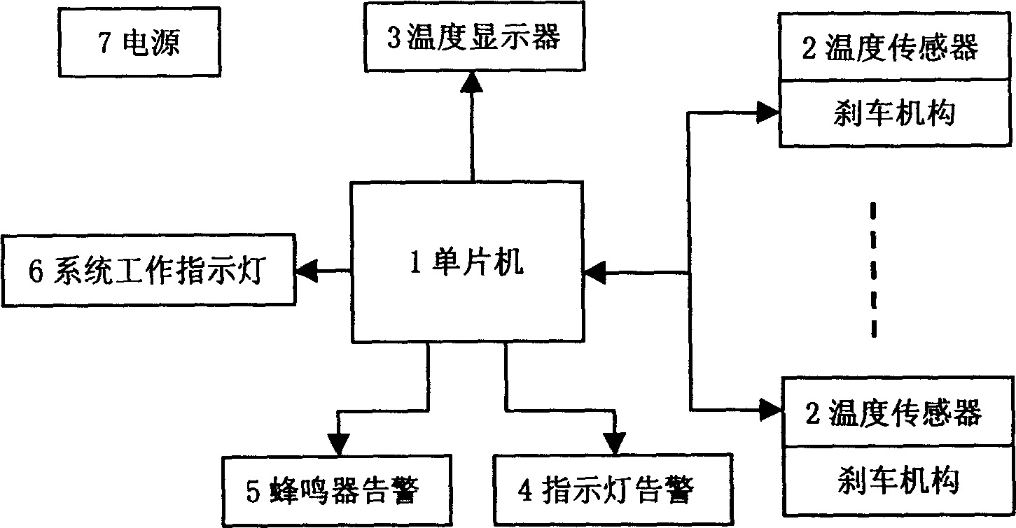
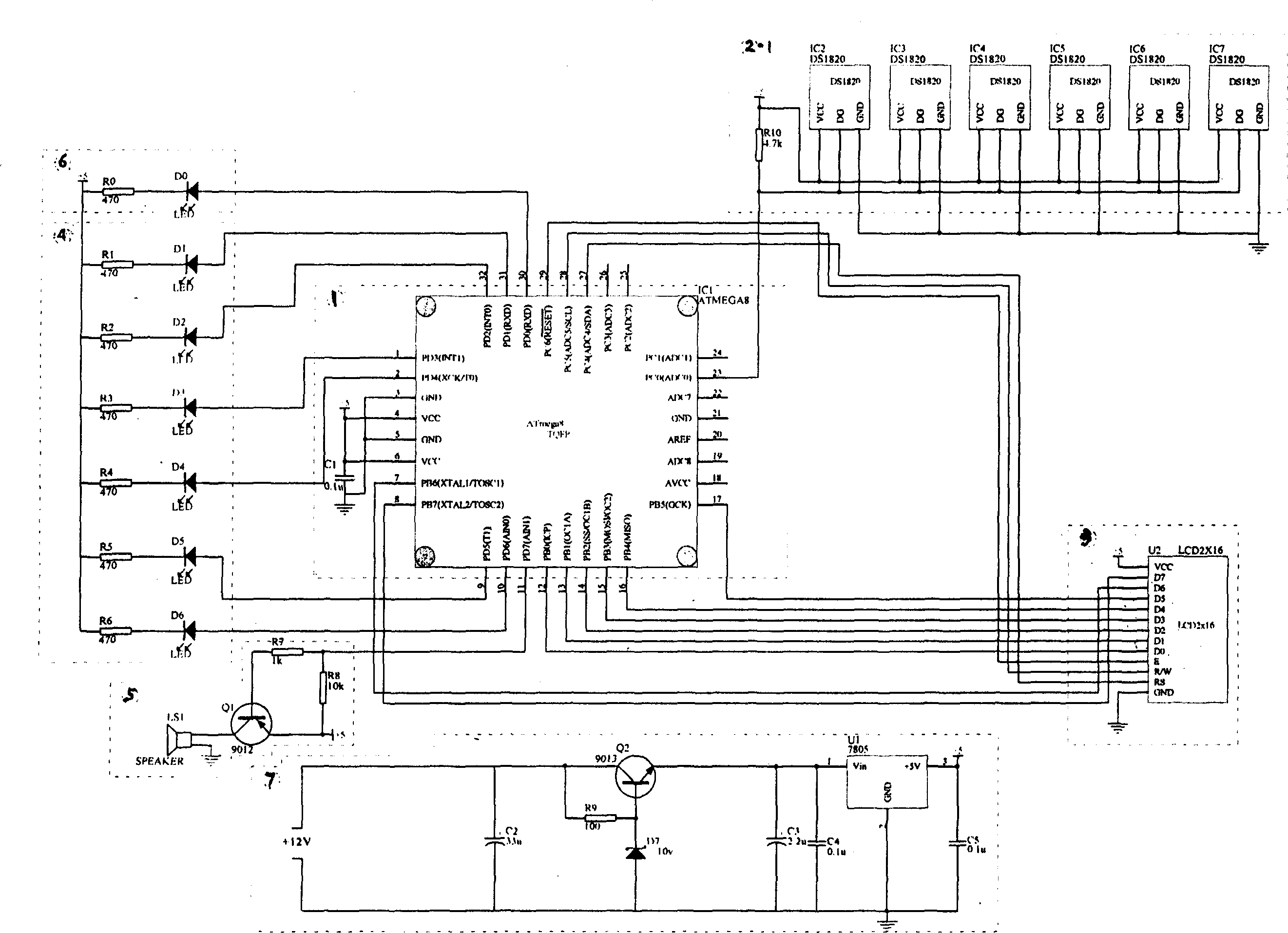
[0020] A motor vehicle brake system fault monitoring device composed of numerical temperature sensors (the circuit schematic diagram is shown in figure 2 shown). Consider according to 6 wheel braking mechanisms in the figure, also can be 4 or 8 wheel braking mechanisms in implementation, only need to increase or decrease the sensor and get final product. In the figure: Atmega8 is an industrial-grade 8-bit microcontroller (IC1), with its own internal crystal oscillator and reset circuit, its own 8k program memory (Flash), 0.5k EEPROM and 1kRAM, making the circuit configuration very simple. The PC0 pin of the single chip microcomputer 1 is used to read the value of the temperature sensor DS1820 (IC2~IC7), the PB0-PB7 pin and the PC4-PC6 pin are used to drive the liquid crystal display (U2) 3 to display the temperature of each wheel brake mechanism, and the PD7 pin is used Drive the buzzer (LS1) 5 to send out the abnormal sound alarm of the brake mechanism, the PD1-PD6 pins are...

Embodiment 2

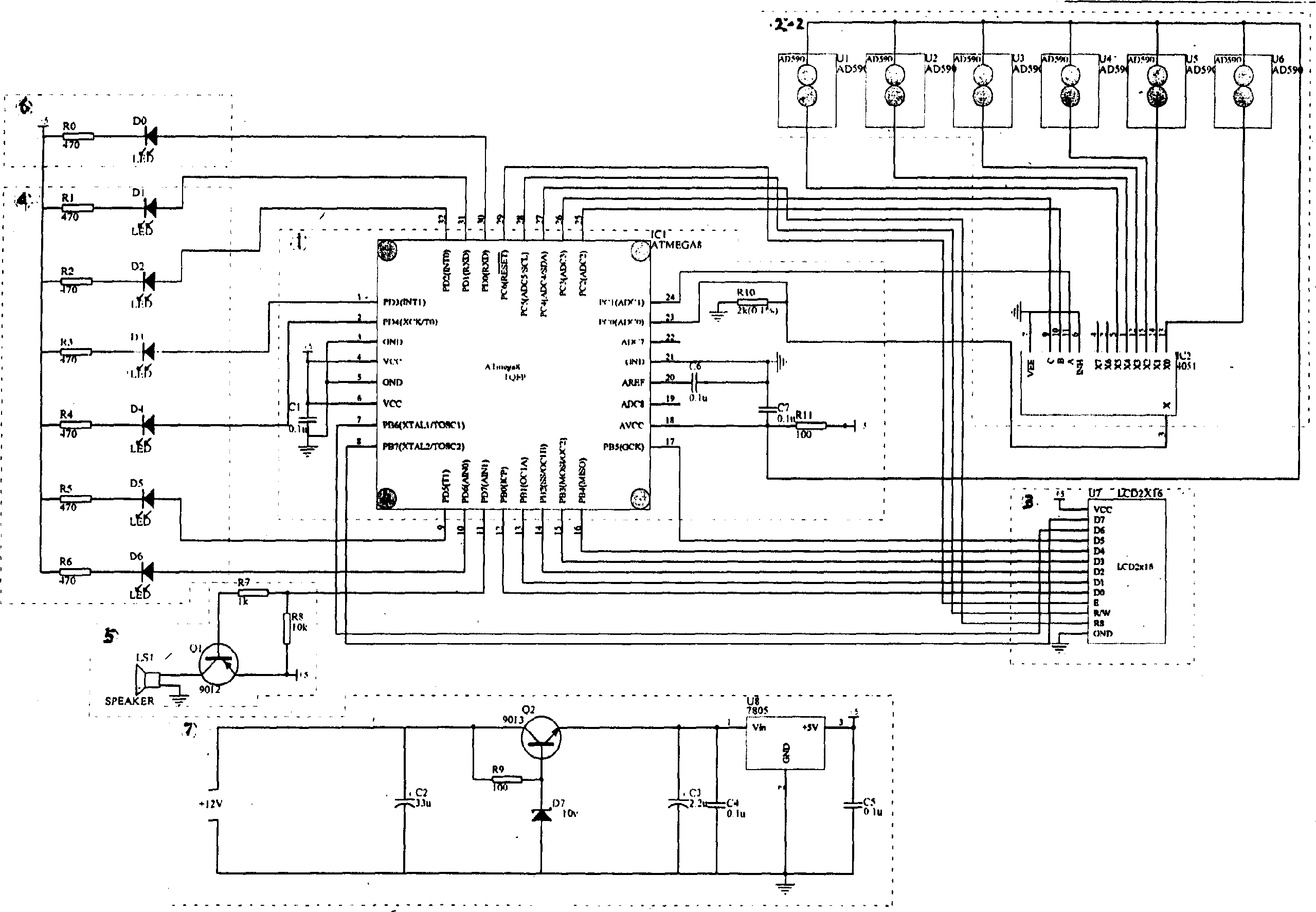
[0022] The schematic diagram of the motor vehicle brake system fault monitoring device composed of analog temperature sensors is as follows: image 3 shown. Consider according to 6 wheel braking mechanisms in the figure, also can be 4 or 8 wheel braking mechanisms in implementation, only need to increase or decrease the sensor and get final product. Use Atmega8 single-chip microcomputer 1 (IC1) identical with embodiment 1, this single-chip microcomputer built-in 4 roads 10 A / D converters, analog temperature signal is carried out A / D conversion, in order to adapt to the motor vehicle with more than 4 braking mechanisms, adopt 4051 (IC2) multi-way switch and 1-way single-chip built-in A / D converter (PC0 pin of IC1), sampling all analog temperature sensors, U1~U6 of 6 temperature sensors 2 are connected to x0~x5 pins of IC2, The pins PC1, PC2, and PC3 of IC1 are connected to pins A, B, and C of IC2, which are used to gate the sensor. Other connections and functions of the singl...


PUM


Abstract

The present invention relates to one kind of early on-line brake system fault monitoring method and device for motor vehicles. Temperature sensor and electronic circuit are used in real-time monitoring and display of the temperature of wheel braking mechanism, photoacoustic warning abnormal temperature of failed braking mechanism and realizing the on-line detection of fault in braking system. The device includes temperature sensors installed onto the braking mechanisms, temperature measuring, display and warning circuit with monolithic computer in the driver cab, connecting wire and power source circuit. The monitoring device may be also used in motor vehicle maintaining unit for detecting braking system.

Description

technical field [0001] The invention relates to an on-line fault monitoring method and device for a motor vehicle braking system realized by the principle of temperature difference. Background technique [0002] Existing motor vehicle brake systems do not have an online fault monitoring device. If a brake system fault cannot be detected and repaired in time, it will affect driving safety, and may even lead to car crashes and death. [0003] Motor vehicle brake systems generally adopt hydraulically driven disc or drum brake mechanisms. The disc brake mechanism pushes the brake pads (brake blocks) through hydraulic pressure to rub against the brake disc to produce a braking effect, and the drum brake mechanism pushes the brake pads (brake pads) through hydraulic pressure. moving shoe) friction brake drum to produce braking effect. If there is a problem with the brake of a certain wheel of a motor vehicle, it must be manifested as an abnormal braking torque. Due to the large f...

Claims


Application Information

Patent Timeline
Patent Type & Authority Applications(China)
IPC IPC(8): B60T17/22
Inventor 王元虎刘劲
Owner 王元虎
Learn More