Middle high pressure directly-acting hydraulic overflow valve

A direct-acting, relief valve technology, applied in the field of pressure control valves, can solve problems such as vibration, noise, working stability, inability to use seawater, and easy polarization of the valve core.

Active Publication Date: 2005-01-12
WUHAN MAJOR DAY DIGITAL MACHINERY MFG CO LTD
View PDF0 Cites 23 Cited by
  • Summary
  • Abstract
  • Description
  • Claims
  • Application Information

AI Technical Summary

Problems solved by technology

However, the spool is easy to polarize, and the resulting vibration, noise and work stability problems still exist
In addition, the material used in the valve cannot be seawater, it is only suitable for fresh water or high water base and other less corrosive media

Method used


Image

  • Middle high pressure directly-acting hydraulic overflow valve
  • Middle high pressure directly-acting hydraulic overflow valve
  • Middle high pressure directly-acting hydraulic overflow valve

Examples


Embodiment Construction

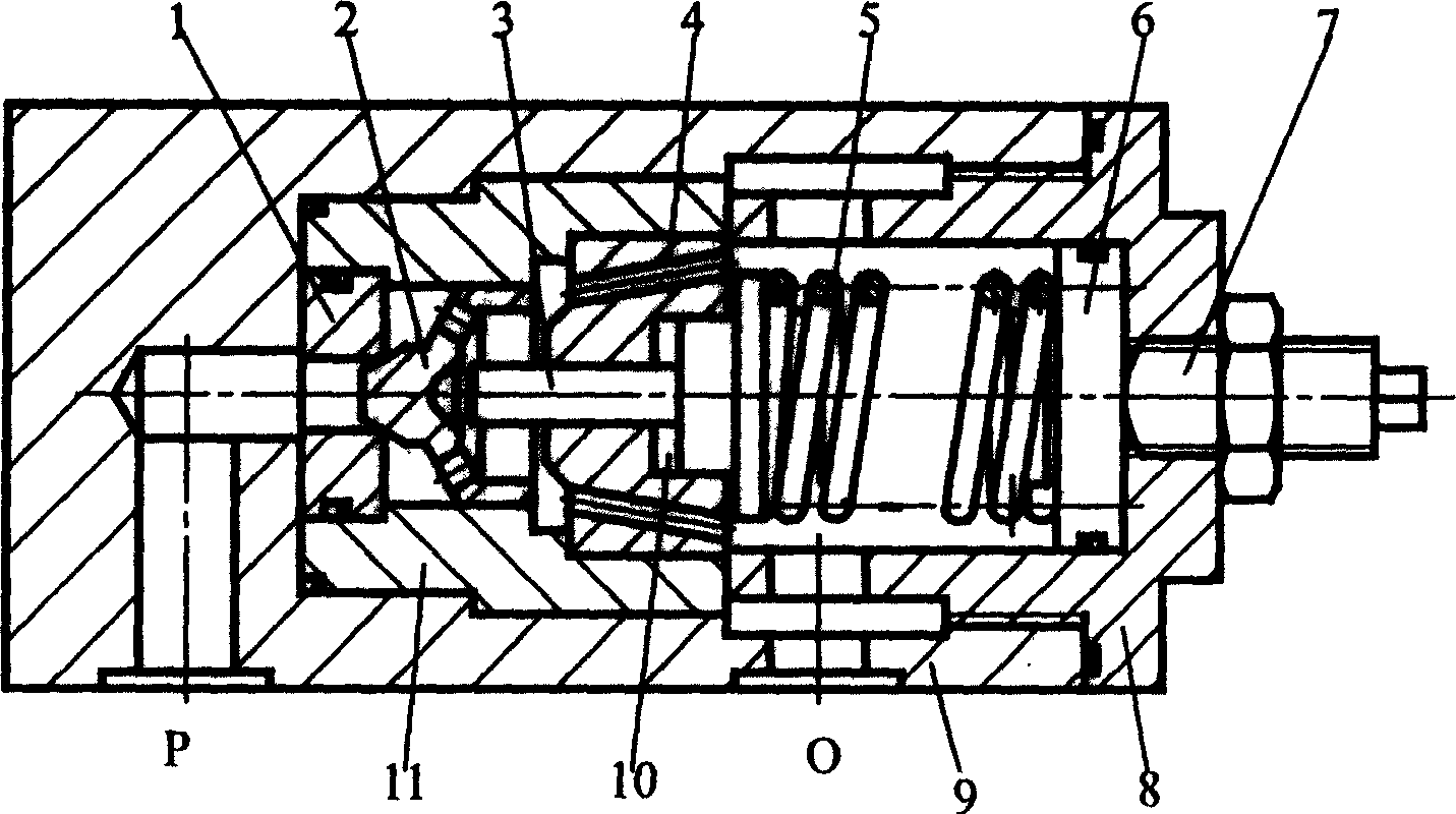
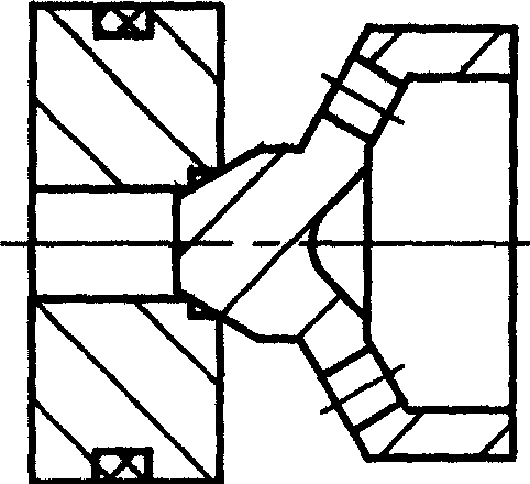
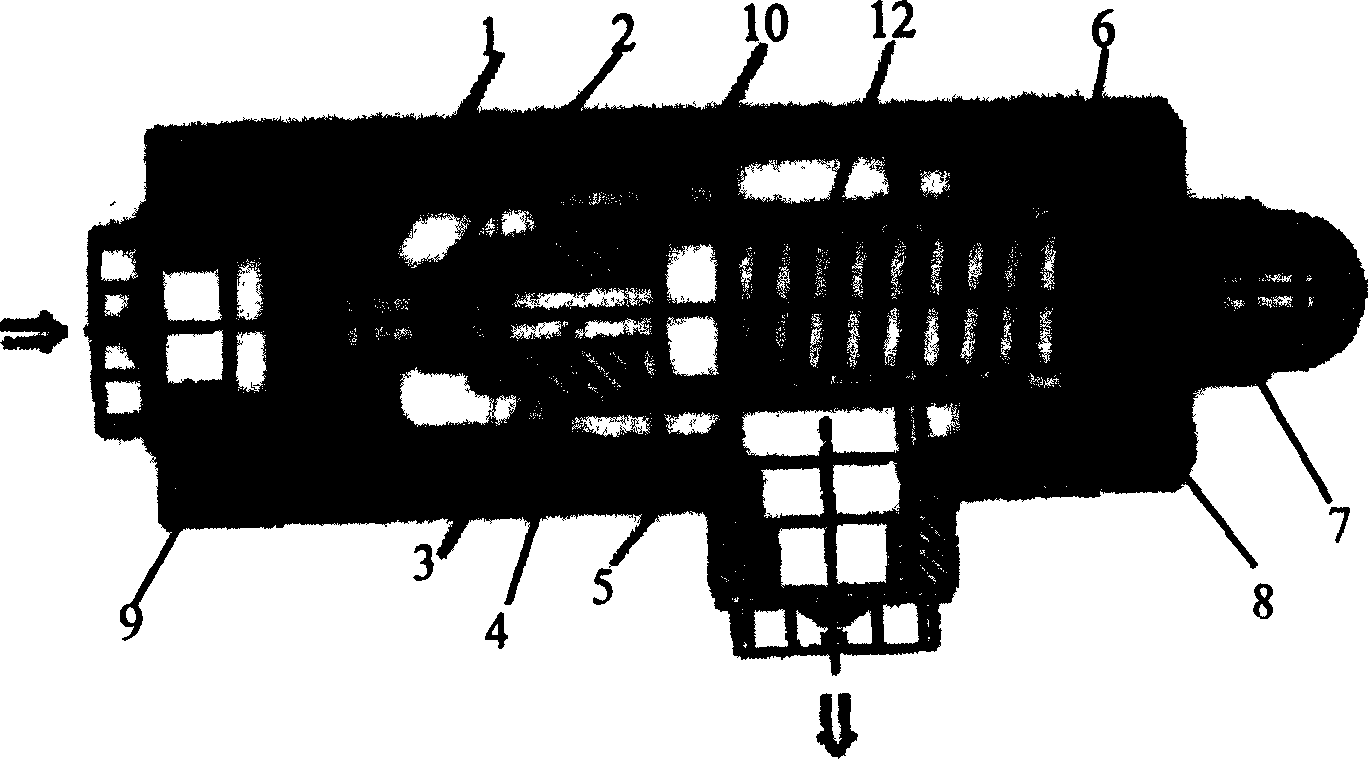
[0017] like figure 1 As shown, an embodiment of the present invention includes: valve seat 1, valve core 2, damping rod 3, damping sleeve 4, pressure regulating spring 5, spring seat 6, adjusting screw rod 7, end cover 8, valve body 9, valve sleeve 11 etc. The spool is a cone valve structure. The tail end of the valve core is provided with a guiding cylindrical surface, which forms a matching gap with the inner hole of the valve body to provide guidance for the movement of the valve core. A damping rod is arranged at the rear end of the spool, and a matching gap is formed between the large and small cylindrical surfaces on the damping rod and the corresponding inner holes of the damping sleeve, and the cavity between the two matching gaps forms a damping chamber 10 . The contact part on the damping rod and the valve core is a spherical structure. When assembling, the valve seat 1 is pressed on the left end surface of the inner hole of the valve body 9 through the valve sle...


PUM


Abstract

The present invention relats to pressure control element in hydraulic system and belongs to the field of valve. The present invention includes valve seat, valve core, damping rod, damping sleeve, valve sleeve, pressure regulating spring, spring seat, end cap and regulating screw. The valve core is one cavity; the damping rod and the damping sleeve have their inner holes form fitting interval and damping cavity; the valve seat and the valve core form one conic valve structure; and the valve core has small holes in its shoulder and tail end forming guide surface to the inner hole of the valve sleeve. The present invention is suitable for use as pressure controlling valve in high and medium pressure hydraulic system with water-based work medium. Compared with similar overflow valves, the present invention has the advantages of less leakage, high cavitation erosion resistance, less vibration, low noise and stable work performance.

Description

technical field [0001] The invention relates to a pressure control element in a water hydraulic system, which belongs to the valve category and is suitable for use as a pressure control valve in a medium-high pressure water hydraulic system using seawater, fresh water, high water base, etc. as working media. Background technique [0002] Relief valve is a commonly used pressure control component in hydraulic system, which can be used as constant pressure relief valve or safety valve. Traditional relief valves mostly use hydraulic oil as the working medium. When the relief valve uses water (water-based) medium (including seawater, fresh water or high water-based, etc.), the cavitation problem is more prominent than that of the oil pressure relief valve. This is because the vaporization pressure of water is much higher than that of mineral oil. When water flows at a high speed at the valve port, the local pressure of the flow field will be lower than the vaporization pressure ...

Claims


Application Information

Patent Timeline
Patent Type & Authority Applications(China)
IPC IPC(8): F16K17/06
Inventor 贺小峰李壮云朱玉泉刘银水朱碧海
Owner WUHAN MAJOR DAY DIGITAL MACHINERY MFG CO LTD
Why Eureka
Try Eureka