
Method of fluidizing wind at high pressure using steam to replace air

A fluidized wind and high-pressure technology, which is applied in the direction of combustion methods, fluidized bed combustion equipment, and fuel burned in a molten state, can solve problems such as air duct vibration, coking, and burnout of the hood of the feeder, so as to avoid vibration and noise, improve the operating environment, and increase the effect of desulfurization efficiency

Inactive Publication Date: 2005-01-19
SHANGHAI BOILER WORKS
View PDF0 Cites 10 Cited by
  • Summary
  • Abstract
  • Description
  • Claims
  • Application Information

AI Technical Summary

Problems solved by technology

In particular, most circulating fluidized bed boilers currently use high-temperature adiabatic cyclone separators. During operation, it is found that the ash return temperature of the feeder is higher than that of the furnace outlet, and some are 50-100°C higher, resulting in burnt air of the feeder. loss and coking
In addition, due to the high pressure head of the return material fluidization, the power consumption of the fan is high, the noise of the high-pressure head fluidization fan is large, and the vibration of the air duct is serious. Some power plants even found that the air chamber of the return feeder and the The entire feeder was damaged by vibration, which affected the operation of the boiler

Method used


Image

  • Method of fluidizing wind at high pressure using steam to replace air
  • Method of fluidizing wind at high pressure using steam to replace air
  • Method of fluidizing wind at high pressure using steam to replace air

Examples


Embodiment Construction

[0029] Since the boiler itself produces steam, the steam passes through the steam turbine to the generator to generate electricity, so the steam can come from the exhaust steam of the steam turbine or intermediate steam extraction, or from the boiler itself or other source generating devices.

[0030] This example takes the 150MW circulating fluidized bed boiler with intermediate reheating of Shanghai Boiler Works Co., Ltd. as an example. The steam is provided by steam turbine exhaust or intermediate extraction:

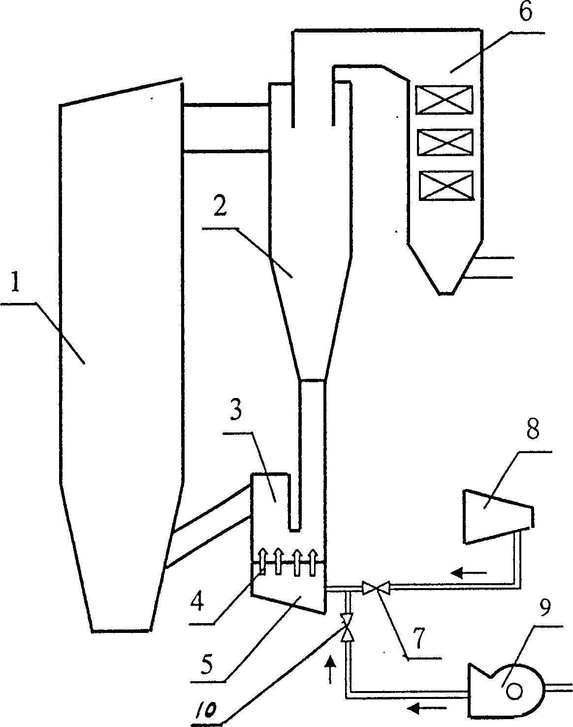
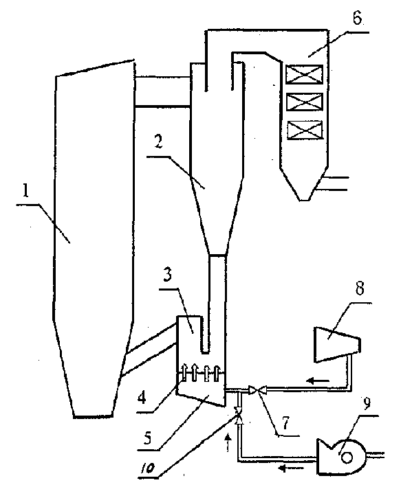
[0031] like figure 1As shown, it is a schematic diagram of a circulating fluidized bed boiler system, which consists of a boiler 1, a cyclone separator 2, a feeder 3, a wind cap and a steam nozzle 4, a wind and steam chamber 5, a tail convection flue 6, a shut-off valve 7, and a steam turbine 8 , a high-pressure fluidizing fan 9, and a shut-off valve 10, the cyclone separator 2 is connected to the upper end of the boiler 1, the upper end of the cyclone separator 2 is...


PUM


Abstract

The invention relates to a method of implementing high pressure fluidization blast using steam in place of air, characterized in that: steam is used for high pressure fluidization blast in normal running of a boiler. The method includes: connecting a turbine exhaust or intermediate extraction with a stock recycler using a steam conduit; starting high pressure fluidization blower and fluidizing recycle material in the stock recycler using air when the boiler begins to start; opening stop valve of the turbine steam conduit, fluidizing recycle material in the stock recycler using steam, shutting down the high pressure fluidization blower and closing the stop valve when the temperature of recycle material in the stock recycler is above 300 Celsius degree, the fluidization steam vapor source pressure parameter is greater than 60Kpa, and the superheat degree is larger than 30 Celsius degree; starting the high pressure fluidization blower, fluidizing recycle material in the stock recycler using air, and closing the stop valve on steam turbine when the temperature of the stock recycler is under 300 Celsius degree in blow off process of the boiler. Advantages of the invention consist in that coking of the stock recycler or other high temperature zones can be prevented or abated and boiler operation reliability can be improved by using steam for replacing high pressure fluidization blast. At the same time, circulating fluid bed boiler desulfurizer utilization rate can be improved, Nox discharge concentration can be reduced, and power plant running cost can be saved by utilizing steam fluidization.

Description

technical field [0001] The invention relates to a method for using steam instead of air to carry out high-pressure fluidization air, which is used for fluidization of a circulating fluidized bed boiler feeder, and belongs to the technical field of circulating fluidized bed boiler fluidization. Background technique [0002] Since the 1980s, circulating fluidized bed boilers have developed rapidly in my country. So far, hundreds of circulating fluidized bed boilers above 130t / h are in operation or are being installed and designed. With the maturity of the combustion technology of circulating fluidized bed boilers, the capacity level of boilers is also increasing. The 135MW circulating fluidized bed boiler with intermediate reheating was also put into commercial operation at the end of 2002. 200MW, 300MW and above circulating fluidized bed The research and development of boilers has also entered the agenda of major scientific research institutes and boiler manufacturers. Practi...

Claims


Application Information

Patent Timeline
Patent Type & Authority Applications(China)
IPC IPC(8): F23C10/00F23C10/22
Inventor 肖峰陈干锦倪晓晖邵国桢
Owner SHANGHAI BOILER WORKS
Learn More