Electroplating compositions and methods
A composition and alloy technology, applied in electrophoretic plating, circuit, electrolytic coating, etc., can solve the problems of precise control of difficult alloy concentration, long processing time, etc.
- Summary
- Abstract
- Description
- Claims
- Application Information
AI Technical Summary
Problems solved by technology
Method used
Image
Examples
Embodiment 1-3
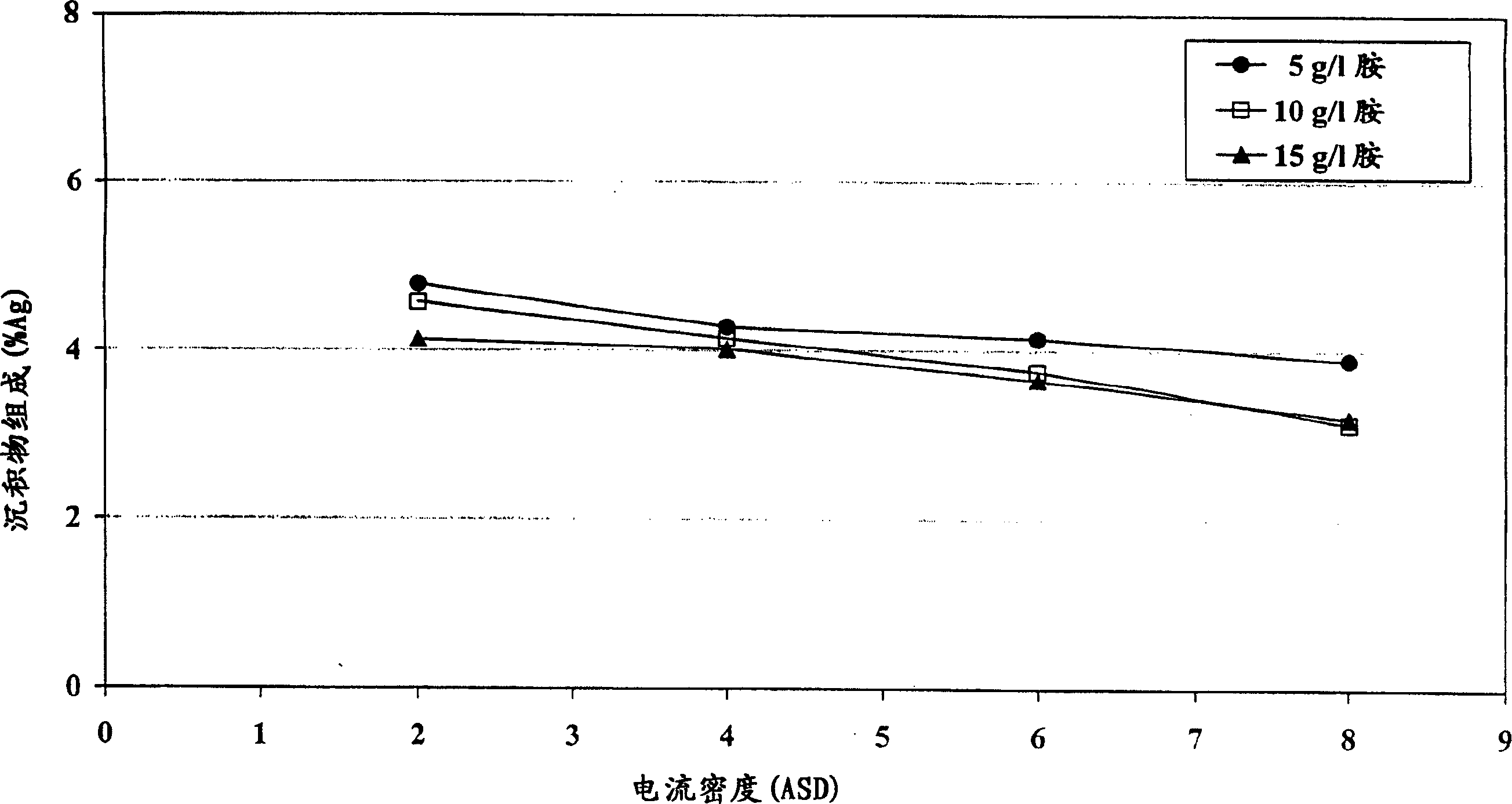
[0070] The electrolyte composition was prepared by mixing 60 g / L tin from tin methanesulfonate, 1.5 g / L silver from silver methanesulfonate, 50 g / L methanesulfonic acid, 15 g / L 1-ene Propyl-2-thiourea, 1.04g / L vanadium (IV) acetylacetonate, content of 5, 10 and 15g / L tetrakis (2-hydroxypropyl) ethylenediamine and the balance of deionized water mixed . Immerse the specimen of Hull steel plate into the composition of Hull tank, using 2, 4, 6, 8A / dm respectively 2 The current density is plated with a layer of tin-silver. The concentration of silver in the resulting layer on each sample was determined using XRF. Measurement results such as figure 2 as shown, figure 2 is the relationship between sediment composition and current density. figure 2 It is shown that, in a wide range of current densities, tin-silver deposits can obtain a uniform composition.
Embodiment 4-5
[0071] Embodiment 4-5, comparative example 1
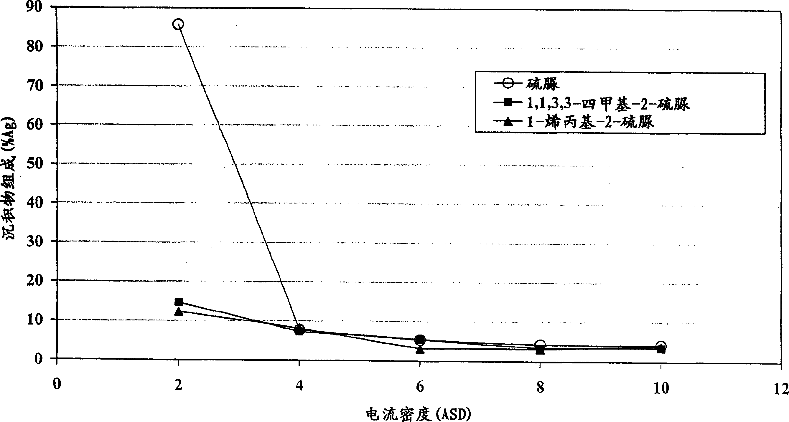
[0072] The electrolyte composition was prepared by adding 40 g / L tin from tin methanesulfonate, 1 g / L silver from silver methanesulfonate, 90 g / L methanesulfonic acid, 2 g / L ethoxy Mix phenol, 4g / L 1-allyl-2-thiourea and the rest of deionized water. Hull steel plates are coated with tin-silver in a composition dipped in a Hull bath. The current densities on the steel plate were determined to be 2, 4, 6, 8 and 10A / dm by XRF 2 The concentration of silver in the resulting layer at the corresponding position of . Respectively replace 1-allyl-2-thiourea with 1,1,3,3-tetramethyl-2-thiourea and 4g / L thiourea (comparative example), to the electrolyte obtained Composition Repeat the above steps. Measurement results such as image 3 as shown, image 3 is the relationship between the composition of the deposit and the current density of the three electrolyte compositions.
[0073] From image 3 It can be seen that at a current dens...
Embodiment 6
[0074] Embodiment 6, comparative example 2
[0075] The electrolyte composition was prepared by adding 40 g / L tin from tin methanesulfonate, 1 g / L copper from copper methanesulfonate, 90 g / L methanesulfonic acid, 2 g / L ethoxy Mix bisphenol, 4g / L 1-allyl-2-thiourea and the rest of deionized water. Hull steel plates were dipped into the composition in a Hull tank and coated with a layer of tin-copper. The current densities on the steel plate were determined to be 2, 4, 6, 8 and 10A / dm by XRF 2 The concentration of copper in the resulting layer at the corresponding location. Using 4 g / L thiourea (comparative example) instead of 1-allyl-2-thiourea, the above steps were repeated for the obtained electrolyte composition. Measurement results such as Figure 4 as shown, Figure 4 is the relationship between the composition of the deposit and the current density obtained by the two electrolyte compositions.
[0076] From Figure 4 It can be seen that at a current density of 2-...
PUM
| Property | Measurement | Unit |
|---|---|---|
| thickness | aaaaa | aaaaa |
| diameter | aaaaa | aaaaa |
Abstract
Description
Claims
Application Information
 - R&D
- Intellectual Property
- Life Sciences
- Materials
- Tech Scout
- Unparalleled Data Quality
- Higher Quality Content
- 60% Fewer Hallucinations
Browse by: Latest US Patents, China's latest patents, Technical Efficacy Thesaurus, Application Domain, Technology Topic, Popular Technical Reports.
© 2025 PatSnap. All rights reserved.Legal|Privacy policy|Modern Slavery Act Transparency Statement|Sitemap|About US| Contact US: help@patsnap.com


