
Manufacturing method of flash memory

A manufacturing method and technology of flash memory, which is applied in the field of flash memory manufacturing, can solve problems such as area reduction, and achieve the effect of improving the coupling rate and increasing the overlapping area

Inactive Publication Date: 2005-01-26
MACRONIX INT CO LTD
View PDF0 Cites 10 Cited by
  • Summary
  • Abstract
  • Description
  • Claims
  • Application Information

AI Technical Summary

Problems solved by technology

[0005] Increasing the overlapping area between the floating gate and the control gate helps to increase the gate coupling ratio. However, with the continuous pursuit of high integration in integrated circuits, the area occupied by each memory cell of the flash memory device must be reduced.

Method used


Image

  • Manufacturing method of flash memory
  • Manufacturing method of flash memory
  • Manufacturing method of flash memory

Examples


Embodiment Construction

[0028] In order to make the above-mentioned and other objects, features, and advantages of the present invention more obvious and easy to understand, preferred embodiments are given below, and in conjunction with the accompanying drawings, are described in detail as follows:

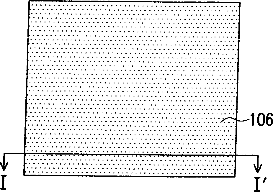
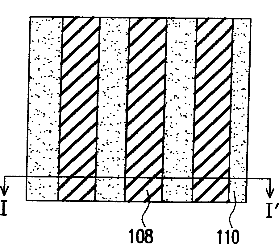
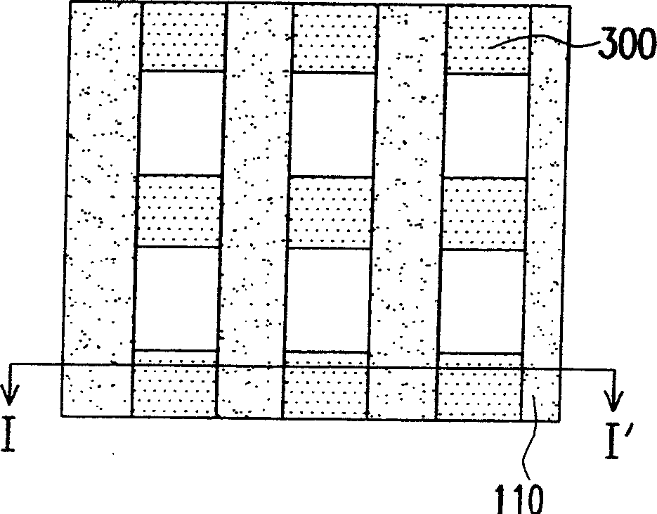
[0029] Figure 1A to Figure 1G A top view of a manufacturing process of a flash memory according to a preferred embodiment of the present invention is shown. Figure 2A to Figure 2G for Figure 1A to Figure 1G A cross-sectional view of the I-I' line. First, please also refer to Figure 1A and Figure 2A , a substrate 100 is provided, and the substrate 100 is, for example, a silicon substrate. Then, a tunnel dielectric layer 102 , a conductor layer 104 and a mask layer 106 are sequentially formed on the substrate 100 . The material of the tunnel dielectric layer 102 is, for example, silicon oxide, and the thickness thereof is, for example, about 50 angstroms to 100 angstroms.

[0030] The formation me...


PUM


Abstract

The invention is a flash memory manufacturing method, in turn forming tunneled dielectric layer, conductor layer and mask layer on a substrate, then patternizing the conductor layer and the mask layer, forming vertically-arranged sticks on the substrate, then forming a buried drain region in the substrate between two adjacent sticks, successively patternizing the sticks, and forming floating grid structure on the substrate, then forming insulating layer around the floating grid structure, where the surface of the insulating layer is lower than the top surface of the patternized conductor layer in the floating grid structure to expose partial surface of side wall around the patternized conductor layer, successively removing the mask layer, forming grid-grid dielectric layer on the conductor layer and then forming control grid on the grid-grid dielectric layer.

Description

technical field [0001] The present invention relates to a method for manufacturing a flash memory, and more particularly, to a method for manufacturing a flash memory that increases the overlap area between the floating gate and the control gate. Background technique [0002] Flash memory devices have become a memory device widely used in personal computers and electronic equipment due to their superior data retention characteristics. [0003] A typical flash memory device is generally designed to have a Stack-Gate structure, which includes a tunnel oxide layer, a polysilicon floating gate for storing charges, silicon monoxide / nitrogen A dielectric layer of an Oxide-Nitride-Oxide (ONO) structure, and a polysilicon control gate (Control Gate) for controlling data access. [0004] In the operation of flash memory, generally the larger the Gate-Coupling Ratio (GCR) between the floating gate and the control gate, the lower the operating voltage required for its operation, and t...

Claims


Application Information

Patent Timeline
Patent Type & Authority Applications(China)
IPC IPC(8): H10B20/00
Inventor 杨令武陈光钊吕瑞霖
Owner MACRONIX INT CO LTD
Learn More