Energy storage means for a yarn guide of a textile machine for producing a cross-wound bobbin

A yarn guide and accumulator technology, applied in the field of accumulators, can solve problems such as the yarn guide being braked, the service life of the spring cannot be reliably enough to meet strict requirements, and the mass and inertia of the laying system will be increased to achieve No effect of mechanical wear

Active Publication Date: 2005-02-09
SAURER SPINNING SOLUTIONS GMBH & CO KG
View PDF2 Cites 4 Cited by
  • Summary
  • Abstract
  • Description
  • Claims
  • Application Information

AI Technical Summary

Problems solved by technology

[0007] Such accumulators of course have various disadvantages: due to the relatively rapid braking of the yarn guides when they hit the respective accumulators, the entire laying system is stressed, for example, and thus must be operated at high speeds. stability, which significantly increases the mass and inertia of the laying system
[0010] However, the rotary spring has been a possible weak point of such a well-adjusted reciprocating device, which works perfectly in theory and in practice, and the service life of this spring may not be reliable enough to meet the requirements proposed for such a laying system. strict requirements

Method used


Image

  • Energy storage means for a yarn guide of a textile machine for producing a cross-wound bobbin
  • Energy storage means for a yarn guide of a textile machine for producing a cross-wound bobbin

Examples


Embodiment Construction

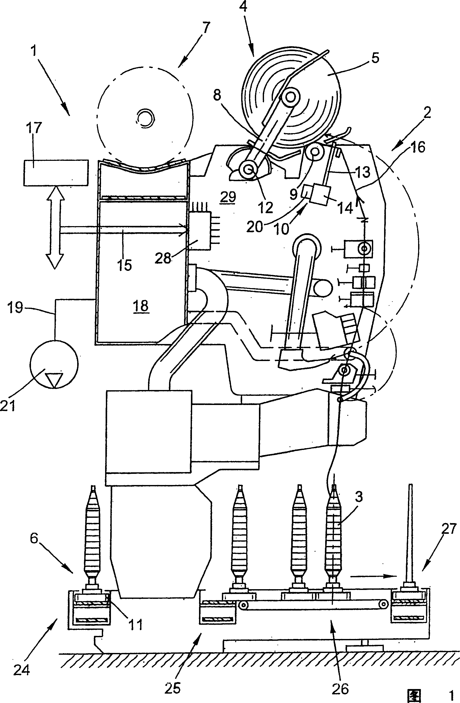
[0023] Figure 1 is a schematic side view of station 2 of a spinning machine for the manufacture of cross-wound bobbins. Here, it is a so-called cross-winding robot 1 . On the station 2 of this cross-winding automatic device 1, as known and thus need not be described in detail, those bobbins 3 produced on a ring spinning machine are rewound into large-volume cross-wraps. Around bobbin 5.

[0024] After completion, the cross-wound bobbin 5 is transferred to a machine-length cross-wound bobbin conveyor 7 by means of a set of (not shown) automatically working maintenance equipment and preferably a cross-wound bobbin changer and sent to a A bobbin loading station or similar device located at the end of the machine.

[0025] The cross-winding robot 1 generally also has a logistics device in the form of a bobbin delivery system 6 . In the bobbin delivery system 6 , the bobbins 3 or empty tubes are moved around on the delivery disc 11 . In FIG. 1 only the bobbin delivery section 2...


PUM


Abstract

This energy accumulator has at least two permanent magnets arranged in fixed positions and one permanent magnet capable of traversing with the finger yarn guide. These permanent magnets are arranged so that poles in the same direction face to each other, and the permanent magnets arranged in the fixed positions are positioned near a motor shaft of an electric mechanical driving device, which is formed with a finger thread guide turning shaft in a left or a right turning range of the finger yarn guide, so that magnetic force of the permanent magnets returns the finger yarn guide to a central area, wherein magnetic force of the permanent magnets are neutral, in the condition that the driving device is disconnected.

Description

technical field [0001] The invention relates to an energy store according to the preamble of claim 1 . Background technique [0002] It is well known that in order to manufacture spinning packages at least two prerequisites must be fulfilled. On the one hand, the spinning package must be rotated and, on the other hand, the yarn wound onto the rotating spinning package must be traversed along the package axis. [0003] If the yarn traverses slowly, a spinning package is formed in which the wound yarns are as parallel as possible. If such a spinning package is to have a relatively large volume and a flat end face arranged substantially perpendicular to the axis of the package, there must be limiting discs on both sides of the winding. If the yarn traverses rapidly so as to form cross-winding, the use of limit discs can be avoided. Since modern spinning machines are known to operate at relatively high winding speeds when making cross-wound bobbins, high traversing rates are ...

Claims


Application Information

Patent Timeline
Patent Type & Authority Applications(China)
IPC IPC(8): B65H54/02B65H54/28B65H54/30
CPCB65H2701/31B65H54/386B65H54/2833B65H2555/13B65H54/2827
Inventor J·霍恩博格
Owner SAURER SPINNING SOLUTIONS GMBH & CO KG
Why Eureka
Try Eureka