Drier

一种烘干机、压缩机的技术,应用在烘干机领域,能够解决阻碍冷却线圈或加热线圈温度控制、难烘干、能源成本高涨等问题,达到缩短烘干时间、提高烘干性能、均匀烘干的效果

Inactive Publication Date: 2005-02-16
SANYO ELECTRIC CO LTD
View PDF2 Cites 12 Cited by
  • Summary
  • Abstract
  • Description
  • Claims
  • Application Information

AI Technical Summary

Problems solved by technology

At this time, the lint floating in the high-temperature and humid air adheres to the cooling coil or heating coil, and there is a problem that the air passage of the circulating air is closed, that is, clogged.
The generation of clogging caused by the thread will hinder the normal temperature control of the cooling coil or heating coil, making it difficult to smoothly dry the desired object
[0009] Therefore, although it is conceivable that as a method of collecting lint floating in the drying air, a mesh-like filter can be provided in the circulation passage of these drying air, there are maintenance procedures such as replacement or cleaning of these filters. cumbersome questions
[0010] However, when using an electric heater or a gas heater for drying operation, the high-temperature air sent into the storage room uses external air with a low temperature outside the storage room and a certain humidity, so the object to be dried is dried. takes a long time
Therefore, the energy consumption for drying the to-be-dried items is large, and there is a problem of high energy costs such as electricity bills and gas bills.
[0011] The heat pump used in Japanese Patent Laid-Open No. 11-99299 can shorten the time required for drying the laundry and is expected to improve energy efficiency. Compared with the heat pump, the heat capacity of the heater system is larger, so there is a problem that it takes time to start the operation from starting the compressor to raising the temperature of the heating coil to a predetermined high temperature and removing moisture from the laundry in the storage room.

Method used


Image

  • Drier
  • Drier
  • Drier

Examples


Embodiment approach 1

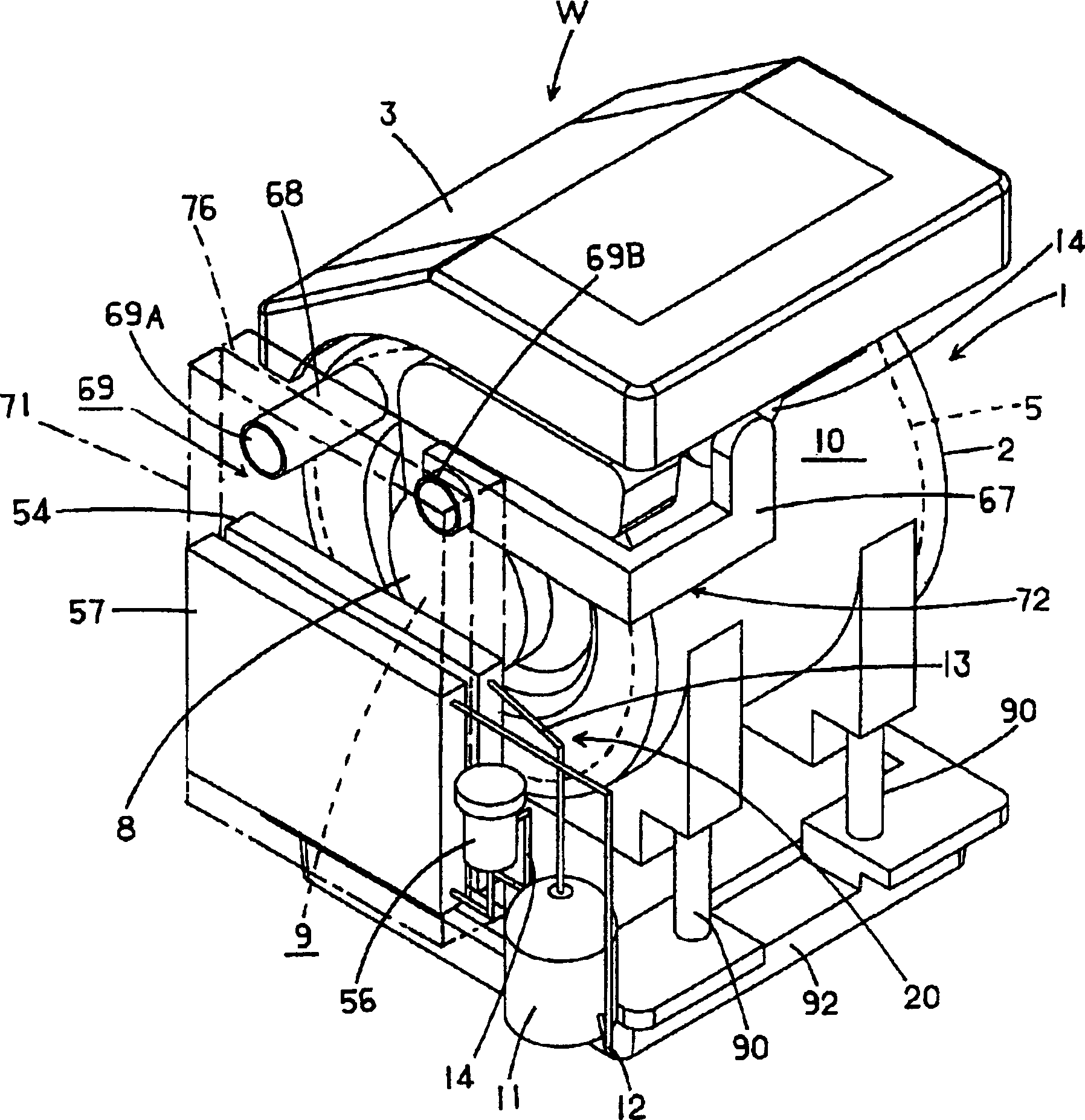
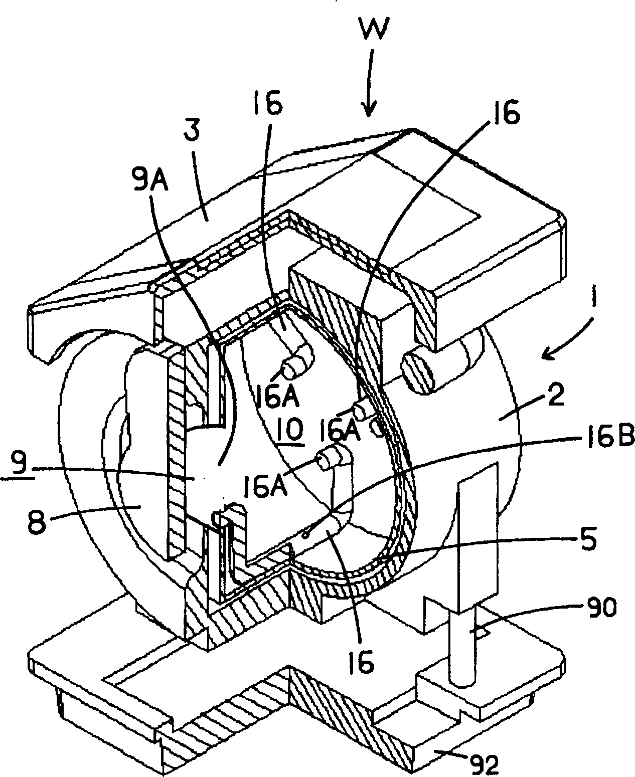
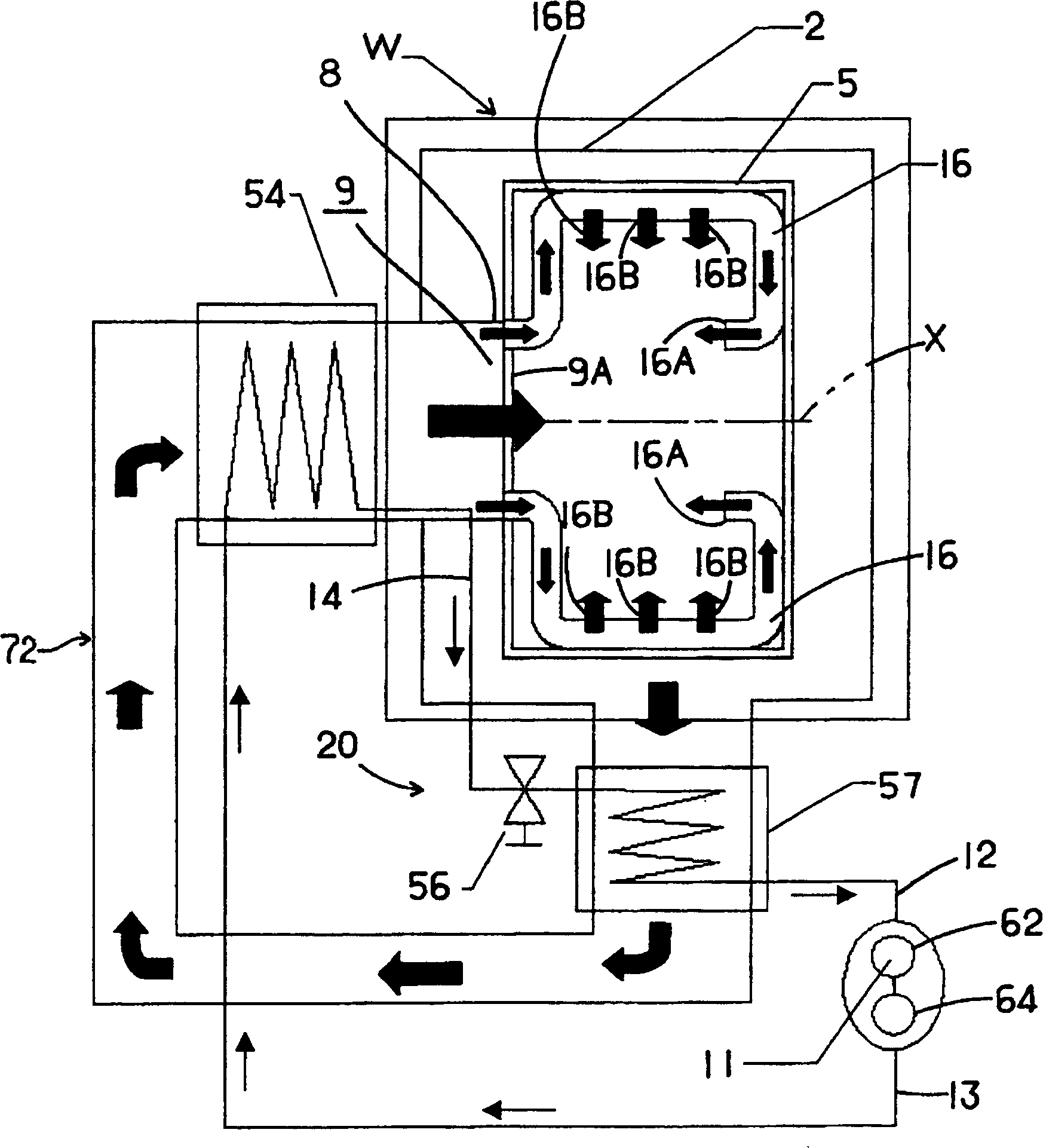
[0065] First, the first embodiment of the present invention will be described in detail with reference to the drawings. figure 1 It is a perspective view showing the internal structure of a washing and drying machine W that performs a washing operation and a drying operation after the completion of the washing operation, to which Embodiment 1 of the dryer of the present invention is applied, figure 2 Yes figure 1 Partially cut-away perspective view of image 3 It is a diagram showing the flow of the refrigerant and drying air in the washing and drying machine W. The washing and drying machine W of the first embodiment is an equipment for washing and drying laundry and other laundry (the laundry becomes the object to be dried during the drying operation). Shows the inside of the casing of the see-through main body 1) is mounted on the upper center part of the opening and closing door 3 for loading and unloading the laundry. On the side of the opening and closing door 3, the uppe...

Embodiment approach 2

[0105] The present embodiment provides a dryer that uses the dew of the evaporator to easily collect the lint floating in the drying air, and prevents clogging of the radiator or the evaporator caused by the lint beforehand. Hereinafter, the present embodiment will be described with reference to a washing and drying machine W that performs a washing operation and performs a drying operation after the completion of the washing operation. Figure 4 It is a diagram of the internal structure of the washing and drying machine W viewed diagonally from the front, Figure 5 It is a diagram of the internal structure of the washing and drying machine W viewed obliquely from behind, Figure 6 It is a circuit diagram showing the refrigerant circuit 26 and the air circulation path constituting the heat pump unit 39.

[0106] The washing and drying machine W is an equipment that washes and dries the laundry such as clothes (the laundry becomes the object to be dried during the drying operation)...

Embodiment approach 3

[0147] This embodiment provides a washing and drying machine capable of shortening the drying time of the laundry. Hereinafter, this embodiment will be described in detail with reference to the drawings.


PUM


Abstract

The invention relates to a drying apparatus. The washing and drying apparatus (W) supplies drying air for a container chamber (10) arranged inside a tank roller (5) so as to dry the dried objects put into the container chamber (10), wherein, spraying nozzles (9A and 16A) for spraying the drying air are arranged at the two sides in the rotating shaft direction of the tank roller (5). Besides, the invention also comprises a spraying nozzle (9A) formed at one side in the rotating shaft direction of the tank roller (5), another spraying nozzle (16A) formed at the other side, and a pipeline component (16) convexly arranged on the inner wall of the tank roller (5) and used for guiding the drying air to the spraying nozzle (16A) formed on the other side from the spraying nozzle (9A) formed at one side, thereby drying the dried objects put into the container chamber of the rotary roller evenly.

Description

Technical field [0001] The invention relates to a dryer having a drying chamber for accommodating objects to be dried. Background technique [0002] In the past, a general dryer used an electric heater as a heat source. After the electric heater heats the outside air to turn it into high-temperature air, it blows it out into the rotating drum that contains the object to be dried, and then dries the object to be dried in the drum. . In addition, the high-temperature air in the drum for drying the object to be dried is dehumidified in the heat exchanger and then used for drying (for example, refer to JP-A 3-202098). [0003] However, in such a dryer, there is a problem that uneven drying of the object to be dried in the rotating drum occurs. Therefore, conventionally, in order to uniformly dry the to-be-dried, the drum is rotated to agitate the to-be-dried inside. However, the drying of the to-be-dried staying at a position far from the outlet of the drying air Dry becomes slower. ...

Claims


Application Information

Patent Timeline
Patent Type & Authority Applications(China)
IPC IPC(8): D06F58/20
CPCD06F58/206
Inventor 友近一善小野公人只野昌也向山洋秋山真一甲元伸央川畑透久保良子
Owner SANYO ELECTRIC CO LTD
Why Eureka
Try Eureka