Optical fibre grating wavelength demodulating method

A fiber bragg grating and wavelength demodulation technology, which is applied in optical demodulation, optics, instruments, etc., can solve the problems of difficulty in design, manufacture and use, steep edges of demodulation filters, and low response frequency, and achieve good cost performance and convenience Promote the application, the effect of fast response

Inactive Publication Date: 2005-02-23
DALIAN UNIV OF TECH
View PDF0 Cites 18 Cited by
  • Summary
  • Abstract
  • Description
  • Claims
  • Application Information

AI Technical Summary

Problems solved by technology

[0010] 4. Edge filtering method, that is, a filter with a large line width and a linear change in transmittance is used to convolve with the reflected light wavelength of the sensor FBG, and the obtained signal is proportional to the position of the FBG peak wavelength, so The FBG wavelength position can be inferred from the signal size. This method requires the edge of the demodulation filter to be very steep and linear, and the parameters of each component of the system are required to be stable. Therefore, it is difficult to design, manufacture and use
In fact, so far, the fiber grating demodulator that can be sold as a commodity in the market only uses a technology of tunable Fabry-Perot filter, and due to the complexity of its technology, the sales of this product The price is very expensive, and the response frequency is not high

Method used


Image

  • Optical fibre grating wavelength demodulating method
  • Optical fibre grating wavelength demodulating method
  • Optical fibre grating wavelength demodulating method

Examples


Embodiment 1

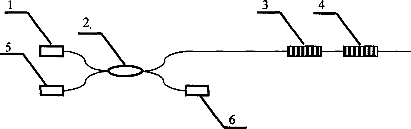
[0027] The present invention is applied to the case of a single measuring point, as attached figure 1 As shown, the light emitted by the broadband light source 1 enters the 2×2 coupler 2, and then enters the photodetector 6, the fiber Bragg grating 3 and the fiber Bragg grating 4 after being split by 2, wherein the fiber Bragg grating 3 is the reference grating, and the fiber Bragg grating 4 is the measurement raster. The center reflection wavelength difference between the fiber grating 3 and the fiber grating 4 is about 1 / 4 of the reflection bandwidth of a single fiber grating. Under the action of the measured fiber grating 4, the reflection center wavelength will move, that is, the difference between the reflection center wavelength of the reference fiber grating 3 and the measurement grating 4 will change, so that the optical power value measured by the photodetector 5 will change. , and then referring to the measured value of the photodetector 6, and removing the influenc...

Embodiment 2

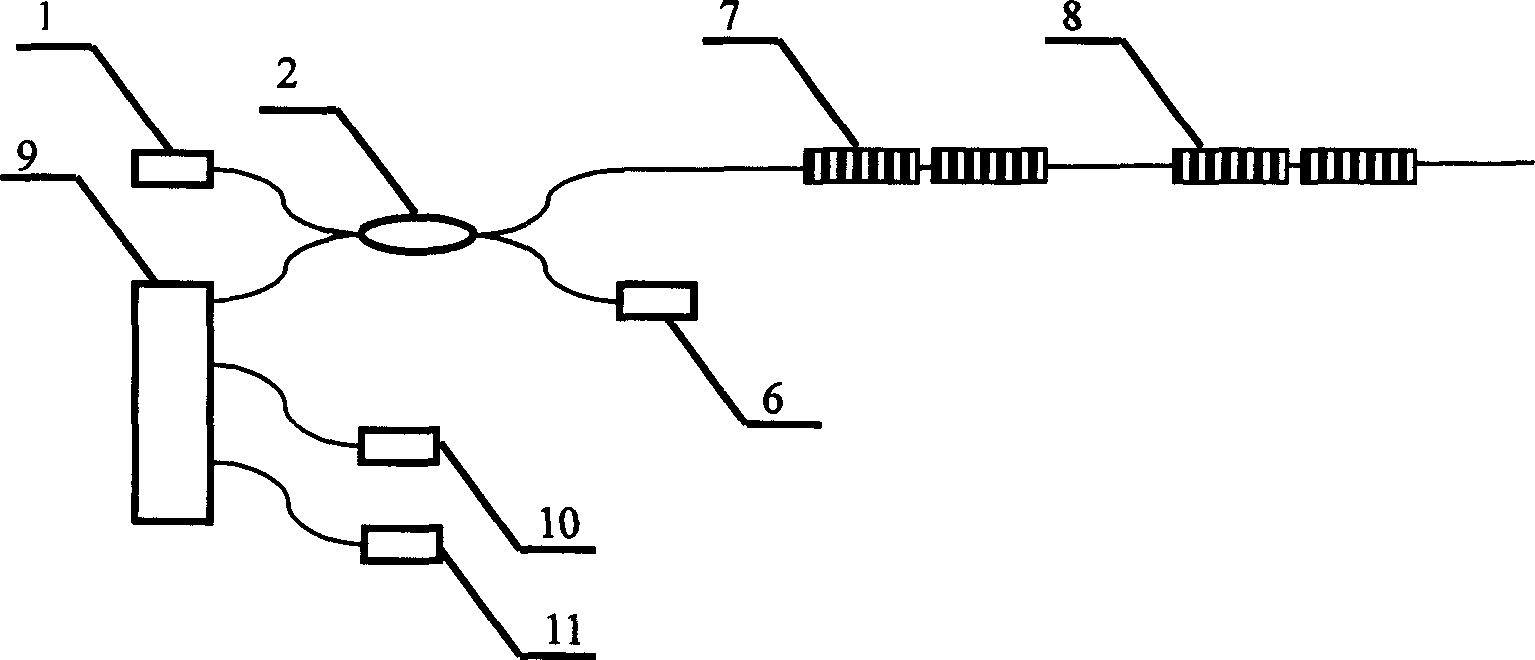
[0029] This example illustrates how to use the present invention to realize distributed fiber grating sensing. as attached figure 2 As shown, the light emitted by the broadband light source 1 enters the 2×2 coupler 2, and after being split by 2, enters the photodetector 6, the fiber Bragg grating pair 7 and the fiber Bragg grating pair 8 respectively, and the fiber Bragg grating pair 7 and the fiber Bragg grating pair 8 are opposite to each other. The center reflection wavelength difference is 1 / 4 of the reflection bandwidth of a single FBG, and the return light frequency ranges of the FBG pair 7 and the FBG pair 8 should be different, so as to ensure that they can be separated by the wavelength division multiplexer 9 . The return light of the fiber grating pair 7 and the fiber grating pair 8 passes through the 2×2 coupler 2 and enters the wavelength division multiplexer 9. The light is separated and enters the photodetector 10 and the photodetector 11 respectively, and the ...


PUM


Abstract

A method for demodulating grating wavelength of optical fibre includes using wideband optical source and a pair of optical fibre connected in series with one as reference and the other as measurement, measuring return power of this pair of optical fibre to obtain reflecting wavelength variation of reference fibre to measurement fibre for achieving wavelength modulation.

Description

technical field [0001] The invention belongs to the technical fields of optical fiber sensing and optical measurement, and relates to a fiber grating wavelength demodulation method. Background technique [0002] A fiber grating is an optical filter with narrow-band reflection characteristics fabricated on an optical fiber. Due to the elastic deformation and thermal expansion characteristics of silica fiber, as well as its thermo-optic and elastic-optic effects, it is sensitive to temperature and stress. Within a certain range, this sensitivity characteristic is linear and conforms to the following relationship: [0003] Δλ ε / λ=ε(1-γ) (1) [0004] Δλ T / λ=(α+e)ΔT (2) [0005] In the formula: ε is the strain of the fiber, γ is the elastic-optic coefficient of the fiber material, α is the thermal expansion coefficient of the fiber material, ΔT is the temperature change, e = 1 n ...

Claims


Application Information

Patent Timeline
Patent Type & Authority Applications(China)
IPC IPC(8): G02F2/00
Inventor 王晓旭赖康生林钧岫
Owner DALIAN UNIV OF TECH
Why Eureka
Try Eureka