Light-spot tracking device of atomic force microscope

A tracking device and light spot technology, which is applied in the direction of measuring devices, instrument parts, instruments, etc., can solve the problems that are difficult to replace, the laser diode cannot be introduced into the observation microcantilever needle tip optical microscope, and the scanner is sensitive to vibration. reasonable effect

Inactive Publication Date: 2005-03-02
SHANGHAI INST OF OPTICS & FINE MECHANICS CHINESE ACAD OF SCI +1
View PDF1 Cites 13 Cited by
  • Summary
  • Abstract
  • Description
  • Claims
  • Application Information

AI Technical Summary

Problems solved by technology

[0005] (2) Prior art 1 cannot introduce an optical microscope for observing the tip of the cantilever and the sample because the laser diode is too close to the tip of the micro-cantilever
[0007] (4) In prior art 1, the scanner will carry laser diodes and photodetectors; in prior art 2, the scanner will ca

Method used


Image

  • Light-spot tracking device of atomic force microscope
  • Light-spot tracking device of atomic force microscope
  • Light-spot tracking device of atomic force microscope

Examples


Embodiment Construction

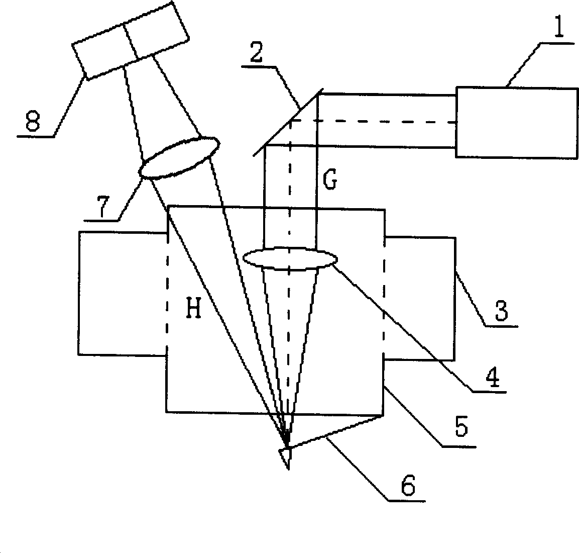
[0027] see first image 3 , image 3 It is a structural schematic diagram of the light spot tracking device of the atomic force microscope of the present invention, as can be seen from the figure, the composition of a light spot tracking device for atomic force microscope tip scanning of the present invention:

[0028] A laser lever: including a laser 1, there is a reflector 2 in the advancing direction of the parallel light beam emitted by the laser 1, the reflector 2 is equipped with an adjustment device, and in the advancing direction of the light G reflected by the reflector 2, there are focusing lens 4 and The micro-cantilever tip 6, the center of the focusing lens 4 and the back top of the micro-cantilever tip 6 are on the optical axis of the light G, and the top of the micro-cantilever tip 6 is located at the focal point of the focusing lens 4, and the reflected light at the micro-cantilever tip 6 On the advance direction of H, there are imaging lens 7 and two-dimensio...


PUM


Abstract

A light spot tracker device is used for tracker device microscope needle point scanning, comprising which consists of laser maser, reflector on the direction of travel of parallel light beams shot by laser maser and it has adjusting device. Focusing lens and microbracket needle point installed is along the direction of travel direction of reflected light of reflector, center of the focusing lens and top of back of the microbracket needle point are on the optical axis of light G and top of the microbracket needle point is on focus of focusing lens. Imaging lens and two-dimensional adjustable four-quadrant photoelectric sensor are on traveling direction reflected light H of microbracket needle point. Unit scanning devices is formed by a XY direction scanner and Z direction scanner fixed on it, and component modularization. The invention has the advantages of simple structure, convenient adjustment and replacement to each component, reliable tracking laser focus light.

Description

technical field [0001] The present invention relates to an atomic force microscope, a light point tracking device for an atomic force microscope. Background technique [0002] Atomic force microscope is a surface measurement instrument with extremely high resolution and many advantages. It is an important basis for the development of nanotechnology and has a wide range of applications. Most of the existing atomic force microscopes use the optical lever detection method to detect the deflection of the micro-cantilever tip after being subjected to atomic force. This method is very mature and has high precision. Especially for atomic force microscopy with sample scanning, this detection method is well realized. However, because the sample is placed on the top of the scanner, the size and weight are limited, thus limiting the application of the sample scanning atomic force microscope. The tip scanning atomic force microscope has many advantages over the sample scanning atomic ...

Claims


Application Information

Patent Timeline
IPC IPC(8): G01Q20/02
Inventor 徐文东杨金涛吉小明
Owner SHANGHAI INST OF OPTICS & FINE MECHANICS CHINESE ACAD OF SCI
Why Eureka
Try Eureka