Array method for drill spindles of printed circuit board drilling machine or forming machine

A printed circuit board, drilling machine technology, applied in the direction of printed circuit, printed circuit manufacturing, drilling/drilling equipment, etc., can solve the problems of increased investment cost, long, sometimes more than 12 hours, low efficiency, etc. To achieve the effect of reducing cost and time and improving efficiency

Inactive Publication Date: 2005-03-16
UNIMICRON TECH SHEN ZHEN
View PDF0 Cites 7 Cited by
  • Summary
  • Abstract
  • Description
  • Claims
  • Application Information

AI Technical Summary

Problems solved by technology

As the printed circuit board becomes larger and the number of holes increases, the drilling time becomes longer and longer, sometimes as long as 12 hours or more, and the e...

Method used


Image

  • Array method for drill spindles of printed circuit board drilling machine or forming machine
  • Array method for drill spindles of printed circuit board drilling machine or forming machine
  • Array method for drill spindles of printed circuit board drilling machine or forming machine

Examples


Embodiment Construction

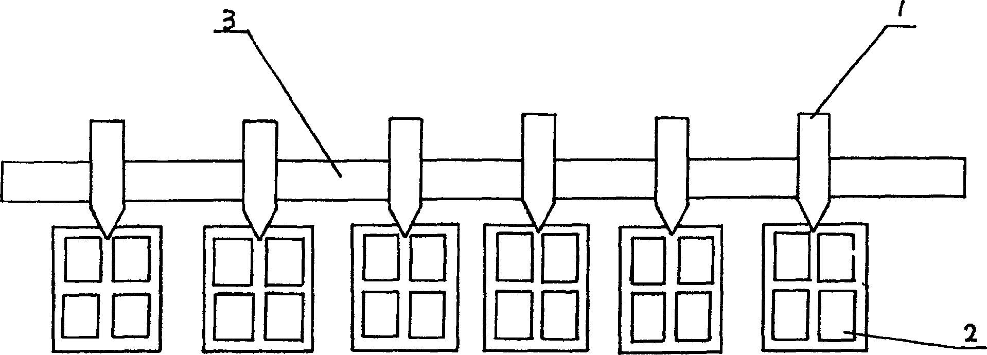
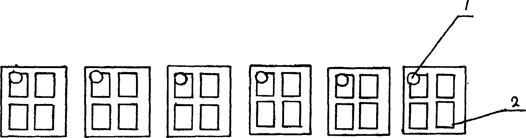
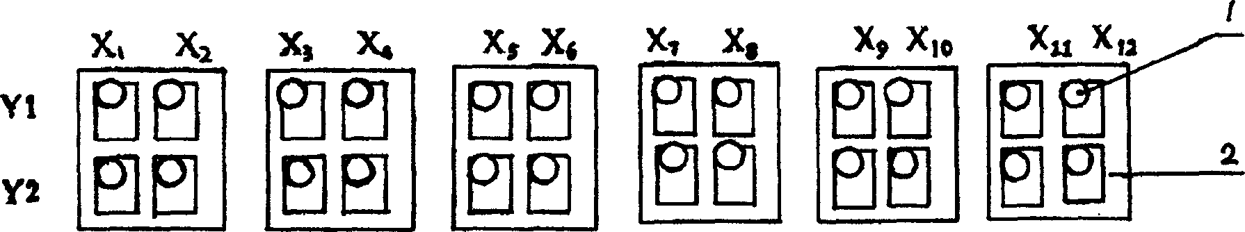
[0014] Such as image 3 , On the drilling machine or molding machine above the printed circuit board 2, the present invention arranges the drilling shafts 1 in a matrix, such as two rows Y1, Y2, and twelve columns X1, X2, -X12. Before drilling, move and adjust the drilling axis according to the layout spacing (drilling spacing). For example, the Y1 row is fixed, and the Y2 row moves as a whole column according to the layout spacing. Columns X4, X6, X8, X10, and X12 are moved as a whole according to the typesetting spacing; of course, all of them can be adjusted. After each axis is set, the drilling operation can be started. In this way, the same drilling machine or molding machine only needs to increase the number of drilling shafts, and the drilling time can be shortened by matrix arrangement. The time spent in this embodiment is 1 / 4 of the original, that is, the efficiency is 4 times of the original. In the future, with the increase of the number of layouts in the board a...


PUM


Abstract

Then invention relates to a kind of arraying method for print circuit board drill or auger spindle of molding machine. It arrays auger spindles in matrix, which is to array auger spindles in several rows and in several lines which both are moveable. The invention improve the drilling efficiency, save the cost and time for drilling, solve the production choke point and cut down the cost of the drilling machine or the molding machine.

Description

Technical field: [0001] The invention relates to a method for arranging drill shafts of a printed circuit board drilling machine or forming machine. Background technique: [0002] The traditional printed circuit board drilling machine or forming machine drill shafts are arranged in a fixed row, the distance between the drill shafts is fixed and cannot be moved and adjusted, and each drill shaft is responsible for punching a piece of printed circuit board (see figure 1 , figure 2 ). As the printed circuit board becomes larger and the number of holes increases, the drilling time becomes longer and longer, sometimes as long as 12 hours or more, and the efficiency appears to be very low, resulting in production bottlenecks and the need to purchase a large number of drills. Hole machine or forming machine, increase investment cost. What was invented: [0003] The purpose of the present invention is to provide a printed circuit board drilling machine or forming machine that ...

Claims


Application Information

Patent Timeline
IPC IPC(8): B23B39/18H05K3/00
Inventor 邱聪进
Owner UNIMICRON TECH SHEN ZHEN
Why Eureka
Try Eureka