High speed power driven magnetic suspension centrifugal blower

A magnetic levitation and centrifugal technology, used in the fields of environmental protection, metallurgy, petroleum and chemical industry, can solve the problems of low efficiency of blower units, and achieve the effect of wide performance adjustment range, small volume and uniform gas supply.

Inactive Publication Date: 2005-03-16
XI AN JIAOTONG UNIV
View PDF0 Cites 19 Cited by
  • Summary
  • Abstract
  • Description
  • Claims
  • Application Information

AI Technical Summary

Problems solved by technology

[0012] In order to solve the outstanding problem of low efficiency of the existing blower uni

Method used


Image

  • High speed power driven magnetic suspension centrifugal blower

Examples


Embodiment Construction

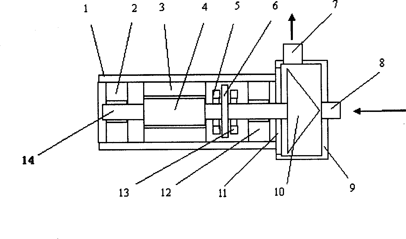
[0021] figure 1 Schematic diagram of the blower. It mainly includes: motor casing 1, first radial bearing 2, motor stator 3, motor rotor 4, first thrust bearing 5, thrust disc 6, exhaust port 7, air inlet 8, volute 9, impeller 10, Back plate 11 , second radial bearing 12 , second thrust bearing 13 , and main shaft 14 .

[0022] There are first radial bearing 2, motor stator 3, second radial bearing 12, first thrust bearing 5, and second thrust bearing 13 in the motor casing 1; the casing 1 passes through a back plate 11 and a volute 9 Connection; along the central axis of the shell space formed by the casing 1 and a volute 9, a main shaft 14 is arranged, and the motor rotor 4, the thrust disc 6, and the impeller matched with the motor stator 3 are sequentially installed on the main shaft 14. 10; the installation position of the impeller 10 is inside the volute 9; the volute 9 is provided with an axial inlet 8 and a radial exhaust 7.

[0023] In the figure, the motor housing...


PUM


Abstract

This invention discloses a magnetically levitated centrifugal fan of high electro motion, which includes: the shell of the electric motor in which there is the first radial axletree, the stator of the motor, the second radial axletree, the first thrust axletree and the second thrust axletree; the shell is connected with a turbine through back tray, a main axis is set on the central axes in the space of the shell, on the main axis there is orderly the rotor of the motor matched with the motor stator, the thrust disk and the impeller; the impeller is in the eddy shell on which the axes-directed air input and the radial directed air output are equipped. This invention use the design of coaxal motor rotor and the thrust disk, the radial axletree and the thrust axletree adopt magnetic levitated axletree or air axletree. This invention has high speed, small cubage, light weight, large flux, high efficiency, convenient charge adjustment and non-pollution.

Description

technical field [0001] The invention belongs to the fields of petroleum, chemical industry, metallurgy and environmental protection, and relates to a blower, in particular to a high-speed electric magnetic suspension centrifugal blower. Background technique [0002] Fan, according to the size of its outlet pressure, it can be divided into ventilator, blower and compressor (or compressor). As the name suggests, it is used as a ventilation / air supply mechanical equipment, which is widely used in various industries, especially in petroleum, chemical industry, metallurgy, aviation, aerospace, environmental protection and other fields. At the same time, it also occupies a very important position in all walks of life, and its role is irreplaceable. However, the current fan products generally have problems such as small capacity, low efficiency, high noise, small performance adjustment range, and high operation and maintenance costs. Among them, fan efficiency is the most importan...

Claims


Application Information

Patent Timeline
IPC IPC(8): F04D25/06F04D27/00F04D29/04
Inventor 王世琥贾友祥
Owner XI AN JIAOTONG UNIV
Why Eureka
Try Eureka