Optical calibrating apparatus and method of laser ranging system

A laser ranging and calibration device technology, which is applied in the direction of measuring devices, radio wave measuring systems, electromagnetic wave re-radiation, etc., can solve the problem of not being able to quantitatively give the coincidence degree of the transmitting and receiving fields of view, and the accuracy of optical calibration is limited, etc. problem, to achieve the effect of protection safety, high work efficiency and high calibration accuracy

Inactive Publication Date: 2005-03-16
SHANGHAI INST OF TECHNICAL PHYSICS - CHINESE ACAD OF SCI
View PDF0 Cites 15 Cited by
  • Summary
  • Abstract
  • Description
  • Claims
  • Application Information

AI Technical Summary

Problems solved by technology

The biggest problem in the traditional method is that the optical calibration work depends entirely on the staff to observe the optical imaging effect with the naked eye to judge the overlapping degree of the transmitting field of v

Method used


Image

  • Optical calibrating apparatus and method of laser ranging system
  • Optical calibrating apparatus and method of laser ranging system
  • Optical calibrating apparatus and method of laser ranging system

Examples


Embodiment Construction

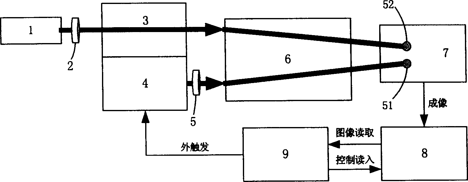
[0030] see first figure 1 , figure 1 It is a structural schematic diagram of the optical calibration device of the laser ranging system of the present invention. It can be seen that the optical calibration device of the laser ranging system of the present invention

[0031] An optical calibration device for a laser ranging system, comprising a receiving optical system 3 and a laser 4, characterized in that the receiving optical system 3 is preceded by a receiving field of view simulation laser 1, and after the receiving optical system 3 and the laser 4 is a collimator 6 After the collimator 6, an image screen 7 is set perpendicular to its main axis, behind the image screen 7 is an area array CCD8, and the area array CCD8 is connected with a computer 9, and the RS322 serial port of the output port of the computer 9 is connected with the laser 4 and the receiving field of view The external trigger source of analog laser 1 is connected. The working process of the device of the ...


PUM


Abstract

It is a laser distance-finding system optics calibration apparatus which comprises receiving optics system and laser and is characterized by the following: there is located with a receiving angular field stimulate laser in front of the receiving optics system; there is located with parallel light tube at the back of the receiving optics system and the laser; there is located with a image screen vertical to its main axis behind the parallel light tube; there is a surface array CCD behind the image screen which is connected with computer; The output end RS322 serial port and laser are connected with the receiving angular field stimulate laser outer trigger power.

Description

Technical field: [0001] The invention relates to laser ranging, in particular to an optical calibration device and method for a laser ranging system. Background technique: [0002] The earth observation laser ranging system is developed from the airborne laser altimetry technology, and the off-machine point height measurement was realized in the early stage, but the accuracy is poor. Due to the popularization of GPS technology, the measurement accuracy has improved rapidly. [0003] The basic working principle of the laser ranging system is: by measuring the time difference between emitting the laser and receiving the laser echo to obtain the distance traveled by the light during the period, and then obtain the distance value. [0004] The performance of a laser altimeter / rangefinder largely refers to its ranging capability, i.e. maximum range. For long-distance laser altimeters / rangefinders (above 20km), the maximum range index is particularly important, which directly de...

Claims


Application Information

Patent Timeline
IPC IPC(8): G01S7/497G01S17/08
Inventor 陈育伟王建宇王岚何志平胡以华张立方抗美舒嵘
Owner SHANGHAI INST OF TECHNICAL PHYSICS - CHINESE ACAD OF SCI
Why Eureka
Try Eureka