
Dual-function electroluminescent device and method for driving the same

An electroluminescent layer and luminescent technology, applied in the direction of electroluminescent light source, electric solid-state device, electric light source, etc., can solve the problems of unstable leakage current, low signal-to-noise ratio, high energy, etc., and achieve the effect of prolonging life

Inactive Publication Date: 2005-04-06
KONINKLIJKE PHILIPS ELECTRONICS NV
View PDF1 Cites 7 Cited by
  • Summary
  • Abstract
  • Description
  • Claims
  • Application Information

AI Technical Summary

Problems solved by technology

[0004] However, the dual function diodes described above have many disadvantages
First, the device described in US-5,504,323 exhibits an asymmetric leakage current characteristic around 0V, and thus the leakage current was found to be unstable
Furthermore, the application of high negative voltage leads to an increased possibility of damage to the device, and the dark current is highly unstable as it is directly related to the damage and short circuit of the organic electroluminescent layer.
This results in a low signal-to-noise ratio for photocurrent detection in reverse operation
But, more importantly, existing devices consume a lot of energy due to the large drive voltage

Method used


Image

  • Dual-function electroluminescent device and method for driving the same
  • Dual-function electroluminescent device and method for driving the same
  • Dual-function electroluminescent device and method for driving the same

Examples


no. 1 example

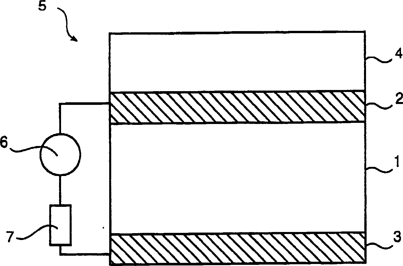
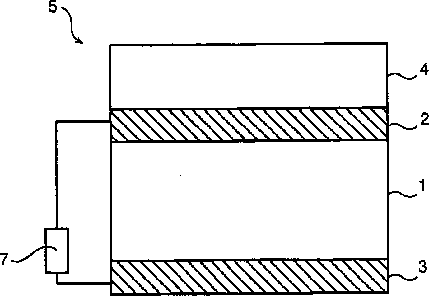
[0042] According to the first embodiment of the present invention, the second driving signal is a voltage V2=0V (short-circuit configuration), that is, zero voltage is applied to both ends of the organic layer 1 . In this state, the two electrodes, now at the same voltage, are separated by the insulating organic electroluminescent layer 1 , for example a polymer layer. However, as long as there is a driving force, there is always a small leakage path in the layer through which a small amount of charge can flow. The aforementioned difference between the work functions of the first and second electrodes causes the electrons in said layer 1 to experience a high binding energy of the first electrode 2 and a low binding energy of the second electrode 3 . Electrons will move from the second electrode to the first electrode and a small transient current (occurring only for a short time) will flow until an equilibrium state is reached. Initially both electrodes are neutral, but since...


PUM


Abstract

This invention relates to a method of driving a dual-function light-emitting and light-sensing device (5) comprising an organic electroluminescent layer (1), such as a polymer layer or a small molecule compound layer, which is sandwiched between a first and a second electrode (2,3), comprising the following steps:-applying, during a emission state (t1), a first emission signal (V1, J1) to said electroluminescent layer (1), said first signal being such that light is generated by and emitted from said electroluminescent layer (1), and-applying, during a sensing state (t2), a second driving signal (V2,J2) to said organic electroluminescent layer (1), said second driving signal being such that the power of said second driving signal has essentially a zero value for accurately detecting an electric current generated in said organic electroluminescent layer when said organic electroluminescent layer is hit by external light This invention also relates to a dual-function light-emitting and light-sensing device and applications thereof.

Description

technical field [0001] The present invention relates to a method of driving a bifunctional light-emitting and light-sensing device comprising an organic electroluminescent layer, such as a polymer layer or a small molecule compound layer, sandwiched between first and second electrodes. The invention also relates to a dual function light emitting and light sensing device. Furthermore, the invention relates to various applications of such displays. Background technique [0002] Organic electroluminescent displays and devices are a relatively newly discovered technology based on the recognition that certain organic materials, such as certain polymers, are used as semiconductors in light emitting diodes. These devices have attracted attention because the use of organic materials, such as polymeric materials, makes them light, flexible, and relatively inexpensive to manufacture. [0003] Recently, it has also been found that such a light-emitting device can be used as a tool fo...

Claims


Application Information

Patent Timeline
Patent Type & Authority Applications(China)
IPC IPC(8): G09G3/20G09G3/30G09G3/32H01L31/10H05B33/12H05B33/14H05B44/00H10K99/00
CPCH05B33/08Y02B20/325H01L51/42H05B33/0896Y02E10/549H05B45/60Y02B20/30H05B44/00H10K30/50H10K30/60G09G3/30H05B33/00H01J40/14H10K30/00
Inventor J·N·休伯特斯A·塞佩P·J·斯尼德H·F·J·J·范汤格恩C·T·H·F·里登鲍姆G·F·A·范德沃尔勒
Owner KONINKLIJKE PHILIPS ELECTRONICS NV
Learn More