Method for determining optical parts normal

A technology of optical components and optical systems, applied in the direction of optical components, optics, optical instrument testing, etc., can solve problems such as low precision, unstable performance of optical systems, and large repetition errors

Inactive Publication Date: 2005-04-27
SHANGHAI INST OF OPTICS & FINE MECHANICS CHINESE ACAD OF SCI
View PDF0 Cites 0 Cited by
  • Summary
  • Abstract
  • Description
  • Claims
  • Application Information

AI Technical Summary

Problems solved by technology

[0003] Especially in large-scale laser projects, hundreds of optical components need to be applied. For example, in high-power OPCPA laser devices and laser nuclear fusion systems, many optical plates and various imaging lenses are used. For these optical plates and imaging lenses, they are The normal line must be concentric and parallel to the optical axis of the entire optical system, which has certain difficulties in actual adjustment and must be adjusted by experienced personnel
[0004] The adjustment method basically adopts the optical reflection method, that is, a beam of visible light, such as a He-Ne laser beam, is concentric and coaxial with the optical system, and then put into the optical components to be used one by one, when the He-Ne laser is incident on the optical components to be used , such as on the surface of an optical flat panel, reflections should be generated. At this time, a screen with fine holes is used to observe the weak reflected beam, and the components to be used are adjusted so that the reflected beam overlaps the incident He-Ne laser beam, which is considered to be a flat panel. The normal line is parallel to the optical axis. The accuracy of this adjustment method depends on the size of the aperture and the distance between the aperture screen and the flat plate to be used. The accuracy is low, which often results in unstable performance of the entire optical system and large repeat errors.

Method used


Image

  • Method for determining optical parts normal

Examples


Embodiment Construction

[0017] Below by embodiment the present invention will be further described.

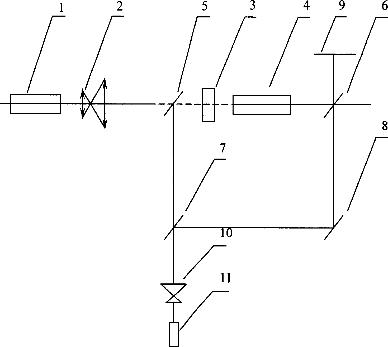
[0018] see first figure 1 , figure 1 It is a schematic diagram of the setting embodiment of the test device in the method for determining the normal line of the optical element of the present invention. In the figure, 1, 2, and 4 are the optical elements that have been placed in the original optical system, and 3 is the optical element to be put into the optical system to be tested. Optical components, such as optical plates or optical imaging lenses. 5, 6, 7, 8 are the four flat plates of the Mach-Zehnder interferometer, 9 is the observation screen, 10, 11 are the beam expander telescope and the He-Ne laser respectively.

[0019] As can be seen from the figure, the method for determining the normal of an optical element in a large optical system in the present invention comprises the following steps:

[0020] 1) The first arm of the Mach-Zehnder interferometer is set in the optical path of the op...


PUM


Abstract

The process of determining the normal line of optical element in a large optical system includes the following steps: setting the first arm of one Mach zehnder interferometer in the optical path for the optical element to be measured with the first plate and the second plate set separately in front of and in back of the optical element to be measured, setting extending telescope and He-Ne laser on the extension line of the fourth arm of the Mach zehnder interferometer and outside the fourth plate, and setting observing screen on the extension line of the second arm of the Mach zehnder interferometer and outside the second plate; turning on the He-Ne laser and regulating the Mach zehnder interferometer to obtain zero-order interference fringe on the screen before the optical element is set in; inserting the optical element; regulating the position of the optical element to obtain immobile interference fringe on the screen and the normal line of the element parallel with the optical axis.

Description

technical field [0001] The invention relates to super-large optical engineering, in particular to a method for determining the normal of optical elements in large-scale optical engineering by using the interference method. Background technique [0002] Since the invention of lasers, laser technology has been widely used in many fields, from material processing to medical equipment, from image recording to entertainment display, from military use to private industry, from single atom lasers to output Pava large CPA lasers Devices, from far-infrared lasers to high-order harmonics in the X-ray band, all kinds of lasers have formed a huge laser market and laser engineering. [0003] Especially in large-scale laser projects, hundreds of optical components need to be applied. For example, in high-power OPCPA laser devices and laser nuclear fusion systems, many optical plates and various imaging lenses are used. For these optical plates and imaging lenses, they are The normal line...

Claims


Application Information

Patent Timeline
Patent Type & Authority Applications(China)
IPC IPC(8): G01M11/00G02B9/02G02B27/00
Inventor 高鸿奕陈建文干慧箐朱化凤李儒新徐至展
Owner SHANGHAI INST OF OPTICS & FINE MECHANICS CHINESE ACAD OF SCI
Why Eureka
Try Eureka