Laser aiming device in free space optical communication system

An optical communication system, free space technology, applied in radio wave measurement systems, instruments, electromagnetic wave re-radiation and other directions, can solve the problems of large and complex optical scanning mechanism, large volume and weight, large amount of information processing, etc., to achieve the scope of application Wide, small size and weight, high measurement accuracy

Inactive Publication Date: 2005-06-08
戴永江 +2
View PDF0 Cites 10 Cited by
  • Summary
  • Abstract
  • Description
  • Claims
  • Application Information

AI Technical Summary

Problems solved by technology

Using a linear array CCD camera requires a huge and complex optical scanning mechanism
Calculate the quality and spatial orientation of the cooperative target through the imaging position of the diagonal reflector of the area array CCD camera within the field of view of the CCD camera, and the number of pixels of the CCD camera limits the resolution of the measurement
The computer has a large amount of information processing and slow measurement speed, which cannot meet the requirements of rapid alignment and adjustment at both ends of the communication chain of the free space optical communication system to ensure communication quality
Large volume and weight, inconvenient to use
[0004] At present, there are no domestic reports, articles or patents on the application of a laser sight composed of a position sensor to both ends of a communication chain composed of a free-space optical communication system.

Method used


Image

  • Laser aiming device in free space optical communication system
  • Laser aiming device in free space optical communication system
  • Laser aiming device in free space optical communication system

Examples


Embodiment Construction

[0022] The embodiments of the present invention will be described in further detail below in conjunction with the accompanying drawings.

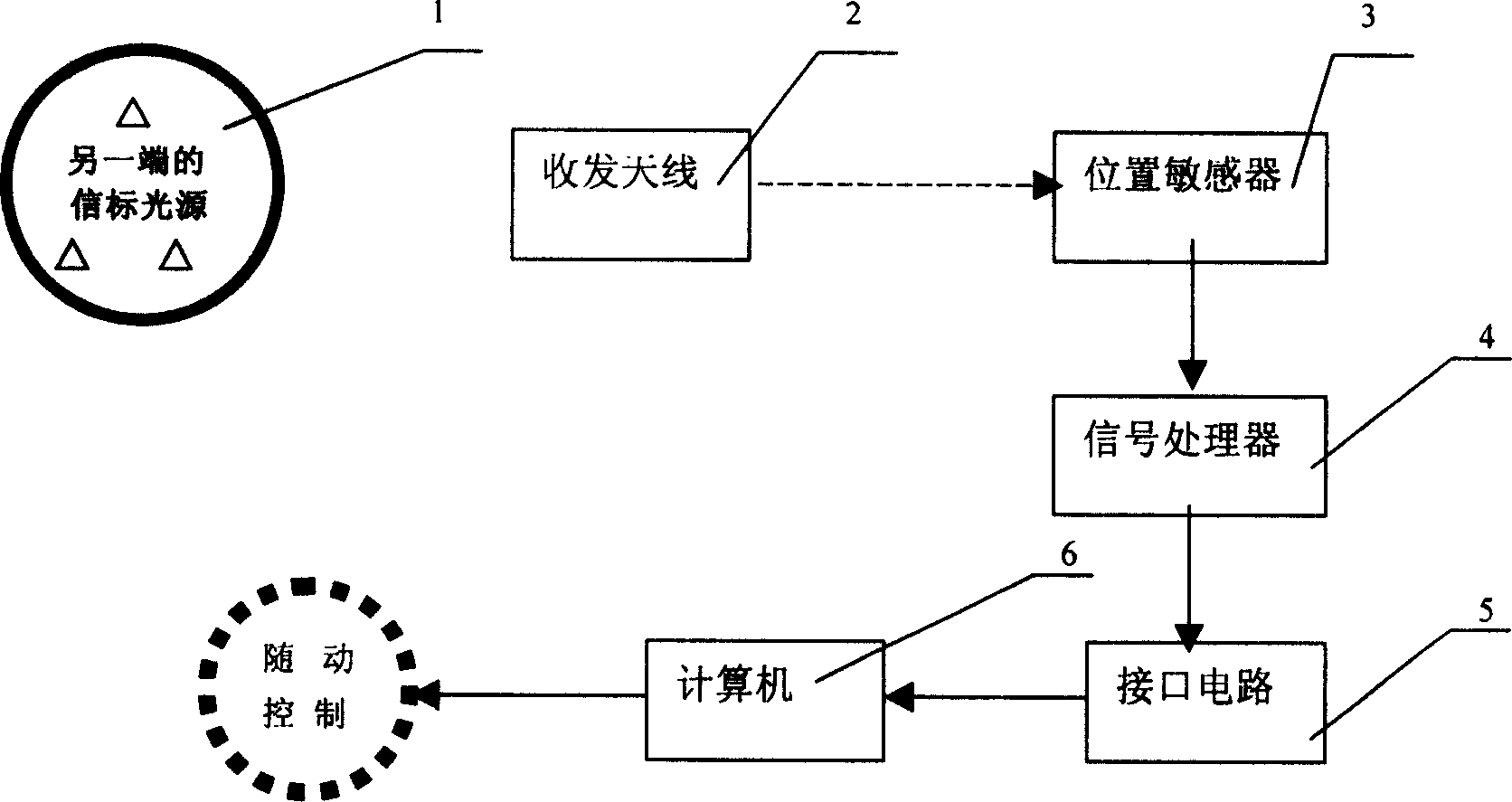
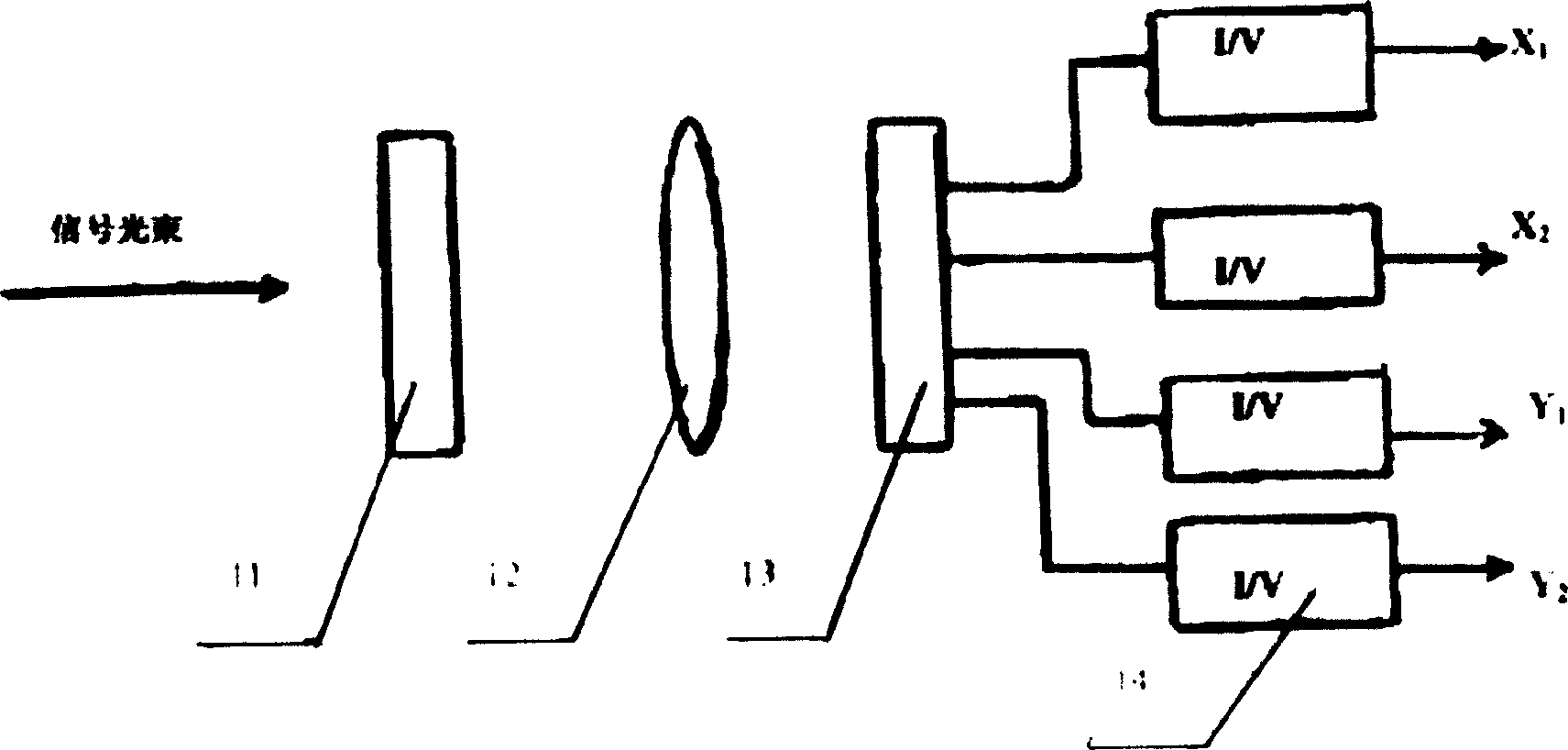
[0023] Depend on Figure 1 to Figure 5 It can be seen that a laser aimer in a free space optical communication system is composed of a modulated beacon light source 1, a receiving optical antenna 2, a position sensor 3, a signal processor 4, an interface circuit 5 and a computer 6, and is characterized in that a pair of The laser beam emitted by the modulated beacon light source 1 at one end of the communication chain formed by the free-space optical communication system is irradiated to the receiving system of another free-space optical communication system at the other end. The system receiving optical antenna 2 focuses on the photosensitive surface of the position sensor 3 to generate a light spot containing the relative position and space attitude azimuth information of the two ends of the free space optical communication system. The po...


PUM


Abstract

A laser aimer of free special optical communication system comprises of modulation beacon light source, receiving optical wire antenna, position sensor, signal processor, interface circuit and computer. The laser beam is generated in the light source on one end of communication link formed of a pair of free special optical communication system, then it irradiates on another end of another free special optical communication system; facula which contains information of the relative position and special angle of the two ends of the system is formed by the system comprising of narrow band filter and imaging lens receiving optical antenna which focuses on the position sensor and photosurface ; the power of facula is changed into electric signal by position sensor and is entered into the electric signal processor to be reprocessed, passed to the computer which will calculate the accurate position and special angle of the two ends. The invention has simple structure, small volume and light weight, high accuracy and fast speed.

Description

[0001] technical field [0002] The invention relates to a tracking and aiming device using laser light. In particular, it relates to a mutual alignment and tracking device for laser transceiver systems at two ends of free space laser communication (Free Space Optical, FSO) or wireless optical communication (Wireless Optical Communication, WOC). Background technique [0003] At present, there are many methods for aiming and position calibration of the transceiver system at both ends of free space optical communication or wireless optical communication, such as the blocking telescope for shooting, but its field of view and aiming distance are limited, and it cannot be operated automatically , need to use manual. Using four-quadrant photoelectric devices to track, there is a blind spot at the center point, and the error is large. Using a linear array CCD camera requires a huge and complex optical scanning mechanism. The quality and spatial orientation of the cooperative targe...

Claims


Application Information

Patent Timeline
Patent Type & Authority Applications(China)
IPC IPC(8): G01S7/497G01S17/88
Inventor 戴永江唐英千戴超
Owner 戴永江
Why Eureka
Try Eureka