Fuel cell with variable porosity gas distribution layers

A fuel cell and gas distribution technology, applied in the field of battery systems, can solve problems such as difficult production and assembly, heavy bipolar plates and PEM components, and high manufacturing costs

Inactive Publication Date: 2005-06-08
GENERAL MOTORS COMPANY
View PDF8 Cites 7 Cited by
  • Summary
  • Abstract
  • Description
  • Claims
  • Application Information

AI Technical Summary

Problems solved by technology

These prior art bipolar plates and PEM assemblies are heavy, l...

Method used


Image

  • Fuel cell with variable porosity gas distribution layers
  • Fuel cell with variable porosity gas distribution layers
  • Fuel cell with variable porosity gas distribution layers

Examples


Embodiment Construction

[0034] DETAILED DESCRIPTION OF THE PREFERRED EMBODIMENT

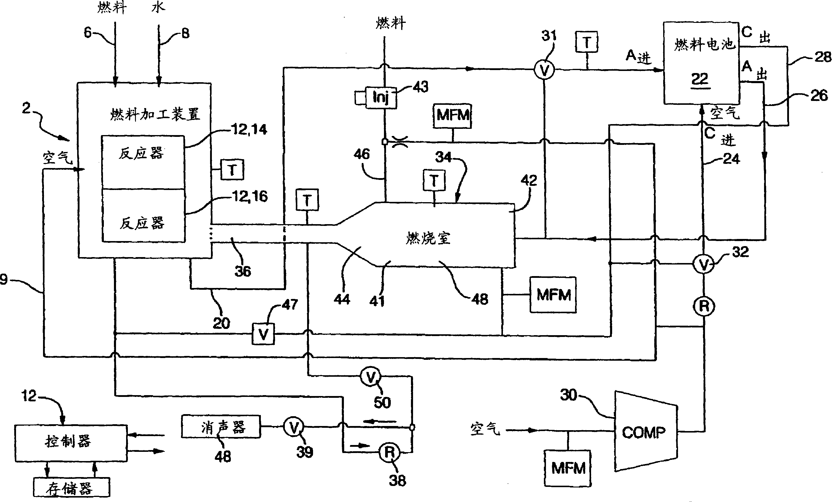
[0035] refer to figure 1 A fuel cell system is shown (by way of example only) to provide a further understanding of the invention. Before further describing the invention, it is therefore useful to understand the system in which the fuel cell of the invention operates.

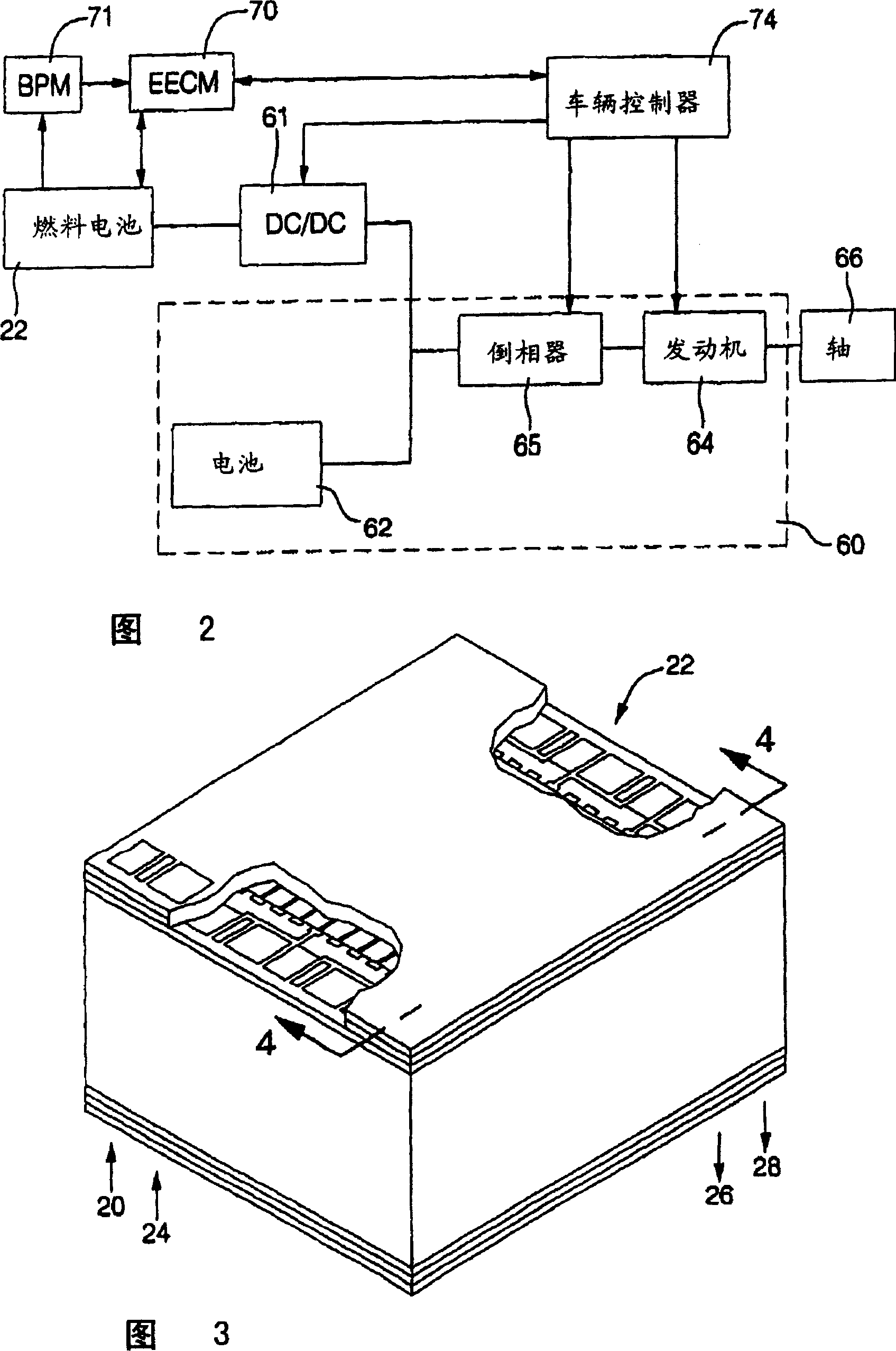
[0036] figure 1 is an example of a fuel cell system. The system can be used in a vehicle (not shown) as a power source for driving the vehicle. In this system, hydrocarbons are processed in a fuel processing unit, such as by reforming and selective oxidation, to produce a reformate gas with a relatively high hydrogen content (volume or molar ratio). Accordingly, reference is made below to hydrogen-rich or relatively high hydrogen content.

[0037] The following will be in the rich H 2 The invention is described within the context of a fuel cell in which reformed gas is used as fuel, regardless of the method by which such reformed gas is produced. ...


PUM


Abstract

A proton exchange membrane fuel cell comprising a proton transmissive membrane, a catalytic anode layer on one face of the membrane, a catalytic cathode layer on the other face of the membrane, and a gas distribution layer on each of the cathode and anode layers defining a gas flow field extending over each of the catalytic layer. Each of the gas distribution layers comprises a layer of open cell conductive foam material which is divided into a plurality of generally parallel segments extending from one edge of the fuel cell to an opposite edge of the fuel cell whereby to define a plurality of generally parallel porous reactant paths extending across each catalytic layer. The segments may be defined by selectively varying the porosity of the foam material or selectively varying the thickness of the foam material. Reactant gases are delivered to the foam gas distribution layer via a manifold structure in which the reactant gases are moved upwardly along an edge of the fuel cell stack in parallel paths and selectively distributed within the stack at the desired cathode or anode levels by selective baffling and partitioning structures.

Description

field of invention [0001] The present invention relates to a fuel cell system, in particular to a fuel cell system with multiple consumption of rich H 2 Gas to generate energy for the battery system. Background of the invention [0002] Fuel cells have been used as power sources in many applications. For example, fuel cells have been proposed for use in electric vehicle power plants in place of internal combustion engines. In proton exchange membrane (PEM) type fuel cells, hydrogen is supplied to the anode of the fuel cell and oxygen is supplied to the cathode as an oxidant. PEM fuel cells comprise a membrane electrode assembly (MEA) comprising a proton-conducting, non-electron-conducting solid polymer electrolyte membrane with an anode catalyst on one face and a cathode catalyst on the other. The MEA is sandwiched between a pair of electrically conductive elements that (1) act as current collectors for the anode and cathode and (2) contain appropriate components for dist...

Claims


Application Information

Patent Timeline
IPC IPC(8): B60L11/18H01M2/14H01M4/86H01M8/02H01M8/04H01M8/06H01M8/10H01M8/24H01M16/00
CPCH01M8/0232H01M8/0234H01M8/0247H01M8/0258H01M8/0265H01M8/0267H01M8/04029H01M8/04074H01M8/0612H01M8/241H01M16/006H01M2300/0082H01M8/1007H01M8/2483Y02E60/10Y02E60/50
Inventor G·W·弗利B·K·布拉迪
Owner GENERAL MOTORS COMPANY
Why Eureka
Try Eureka