Scratch hardness reference device

A reference device and Leeb hardness technology, which is applied in the direction of testing the hardness of materials, etc., can solve the problems of poor long-term stability and low measurement accuracy

Inactive Publication Date: 2005-07-06
中国航空工业第一集团公司三〇四所
View PDF0 Cites 10 Cited by
  • Summary
  • Abstract
  • Description
  • Claims
  • Application Information

AI Technical Summary

Problems solved by technology

[0010] In order to overcome the shortcomings of poor long-term stability and low measurement accuracy of current Leeb hardness testers, the purpose of the present invention is to provide a Leeb hardness reference device with high measurement accuracy and good long-term stability

Method used


Image

  • Scratch hardness reference device
  • Scratch hardness reference device
  • Scratch hardness reference device

Examples


Embodiment Construction

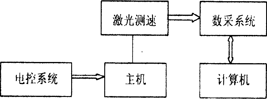
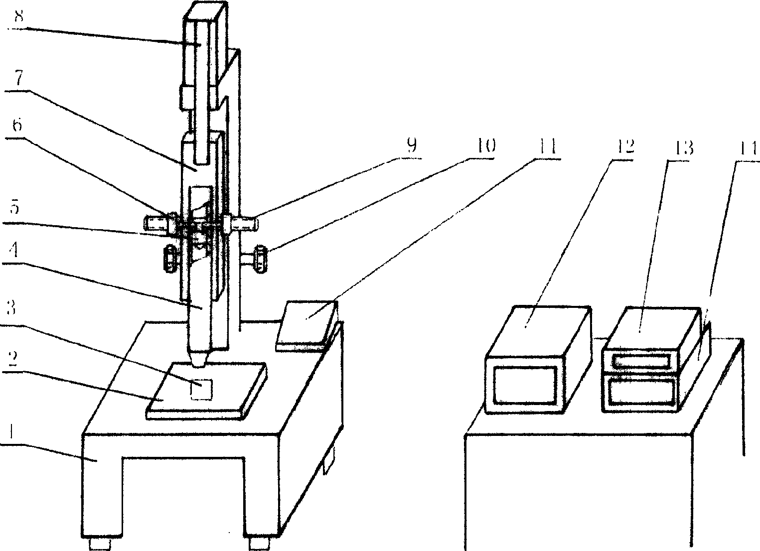
[0020] The present invention is a device with a high degree of automation integrating optical, mechanical and electrical systems, and is composed of a host, an impact body, an electric control system, a laser Doppler speed measurement system, a data acquisition system, and a data processing system. For the structure diagram, see figure 2 .

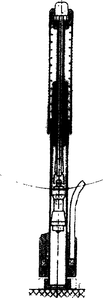
[0021] The main engine consists of a base (1), a worktable (2), a guide cylinder (4), an impact body (5), an impact body release clamping mechanism (6), a lifting guide rail (7), a screw rod (9) and a lifting hand wheel (10) and so on. Its base weighs 400 kg, is firm and stable, and meets the requirements of the Leeb hardness dynamic test. The lifting mechanism and the clamping mechanism are used to release the D-type impact body and the G-type impact body for the verification of the Leeb hardness HLD and HLG scales. The mass of the impact body (5) is 5.5g±0.05g for type D and 20g±0.05g for type G. There is a step on the top, which is ...


PUM

PropertyMeasurementUnit
diameteraaaaaaaaaa

Abstract

This invention relates to Richter hardness basic device, which comprises the following: base socket on the workbench; impact part with tungsten carbide ball head; guiding cylinder to control the impact part radium direction; impact part lift clamper structure; control device; speed test device and data collection device, wherein the impact part gets energy form the gravity and the speed test device adopts the laser Doppler speed test system.

Description

technical field [0001] The invention relates to a hardness measuring device, in particular to a reference device for measuring the Leeb hardness of a test piece, belonging to the technical field of precision measurement. Background technique [0002] The Leeb hardness measurement method was invented by Dr. D.LEB of Switzerland in the late 1970s. It is a dynamic hardness test method based on the principle of energy measurement. The basis of the test principle is to keep a constant energy (D type 11N mm, G type 90N mm) impacts the static material specimen, and then rebounds, and measures the energy (residual energy) existing in the specimen during the rebound, and the residual energy is the Leeb hardness the size of. The Leeb hardness value is defined as: [0003] [0004] Where: HL- Leeb hardness value [0005] V 反 - Bounce speed [0006] V 冲 - impact speed [0007] The portable Leeb hardness tester developed and mass-produced with this test principle is small and e...

Claims


Application Information

Patent Timeline
Patent Type & Authority Applications(China)
IPC IPC(8): G01N3/48
Inventor 石伟王中华徐明张宏运李新良宗惠才
Owner 中国航空工业第一集团公司三〇四所
Why Eureka
Try Eureka