
Method for manufacturing light guiding plate core

A manufacturing method and technology of a light guide plate, applied in the directions of optics, nonlinear optics, microlithography exposure equipment, etc., can solve the problem that the microstructure on the light guide plate is not easy to form, and achieve easy forming, high precision, and guaranteed light output efficiency Effect

Inactive Publication Date: 2005-07-06
HONG FU JIN PRECISION IND (SHENZHEN) CO LTD +1
View PDF0 Cites 8 Cited by
  • Summary
  • Abstract
  • Description
  • Claims
  • Application Information

AI Technical Summary

Problems solved by technology

[0007] In order to overcome the problem that the microstructure on the light guide plate is not easy to form in the prior art, the present invention provides a method for manufacturing the mold core of the light guide plate that can accurately form the V-shaped groove structure of the light guide plate

Method used


Image

  • Method for manufacturing light guiding plate core
  • Method for manufacturing light guiding plate core
  • Method for manufacturing light guiding plate core

Examples


Embodiment Construction

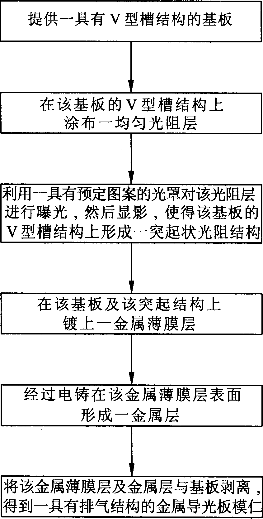
[0018] see figure 2 , is the manufacturing process of the manufacturing method of the mold core of the light guide plate of the present invention, which includes the following steps: providing a substrate with a V-shaped groove structure; coating a uniform photoresist layer on the V-shaped groove structure of the substrate; using a predetermined The patterned photomask exposes the photoresist layer, and then develops it, so that a protruding photoresist structure is formed on the top of the V-shaped groove structure of the substrate; a metal thin film layer is plated on the substrate and the protruding structure; A metal layer is formed on the surface of the metal thin film layer; the metal thin film layer and the metal layer are peeled off from the substrate to obtain a metal light guide plate core with an exhaust structure.

[0019] Please refer to image 3 , provide a substrate 10 with a V-shaped groove structure 11, wherein the substrate 10 is polymethyl methacrylate (Po...


PUM

PropertyMeasurementUnit
thicknessaaaaaaaaaa
thicknessaaaaaaaaaa

Abstract

This invention relates to a light conductive plate mould core method, which comprises the following steps: providing a V shape groove structure base plate; coating an even layer of light resistance on the groove; using a pre-set pattern cover on the layer for exposal and development to make the groove form an extrusion light resistance structure; coating a metal film layer on the base plate; forming a metal layer on the metal film layer through electroform; isolating the metal film layer to the base plate to get the metal light conductive mould core with one exit structure.

Description

【Technical field】 [0001] The invention relates to a method for manufacturing a mold core, in particular to a method for manufacturing a mold core for a light guide plate used in a liquid crystal display device. 【Background technique】 [0002] In recent years, with the colorization and enlargement of liquid crystal displays, their application fields are more extensive, such as notebook computers, various desktop computers, and LCD TVs. Because the liquid crystal display is a passive component, it cannot emit light by itself, so it is necessary to use a light source as the light source of the liquid crystal display, such as the backlight module (BacklightModule), wherein the light guide plate is one of the important components in the backlight module, used to guide The transmission direction of the light emitted from the light source, converting the line light source or point light source into a surface light source to emit. [0003] A general light guide plate includes at le...

Claims


Application Information

Patent Timeline
Patent Type & Authority Applications(China)
IPC IPC(8): G02F1/1335G02F1/13357G03F7/20
Inventor 江宗韦蔡明江李俊佑陈杰良
Owner HONG FU JIN PRECISION IND (SHENZHEN) CO LTD
Learn More