Anode unit for continuous electroplating of belt poor conductor
A technique for anode devices and conductors, applied in the direction of electrodes, etc., can solve problems such as poor conductivity and uneven current density distribution
- Summary
- Abstract
- Description
- Claims
- Application Information
AI Technical Summary
Problems solved by technology
Method used
Image
Examples
specific Embodiment approach 1
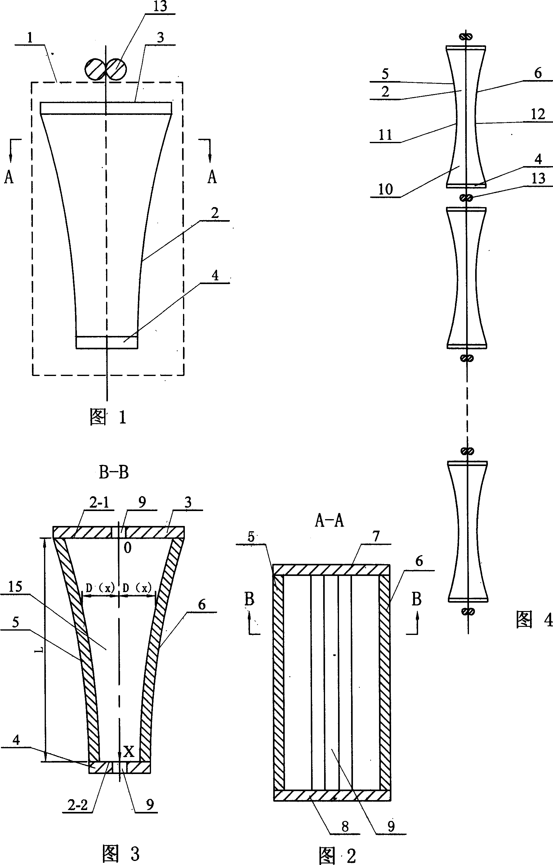
[0005] Specific embodiment 1: Referring to Fig. 1 to Fig. 3, the anode device of this embodiment is composed of at least one anode unit 1, and the anode unit 1 is composed of a through cavity 2, an upper insulating cover plate 3, and a lower insulating cover plate 4, and the through cavity 2 It is surrounded by the first anode plate 5, the first insulating baffle 7, the second anode plate 6, and the second insulating baffle 8 in sequence. The first anode plate 5 and the second anode plate 6 have the same structure, and the first insulator The baffle 7 and the second insulating baffle 8 have the same structure; the upper insulating cover 3 is connected to the upper port 2-1 of the through cavity 2, the lower insulating cover 4 is connected to the lower port 2-2 of the through cavity 2, and the upper Both the insulating cover plate 3 and the lower insulating cover plate 4 are provided with slits 9, the symmetrical planes of the two slits 9 coincide with the symmetrical planes of ...
specific Embodiment approach 2
[0006] Specific embodiment 2: Referring to Fig. 4, the difference between this embodiment and specific embodiment 1 is that a through cavity 10 is added in the anode unit 1, the structure of the through cavity 10 is the same as that of the through cavity 2, and the lower port 2 of the through cavity 2- 2 connects with the upper port 11 of the through cavity 10 in the same arc, and the symmetrical planes of the through cavity 2 and the through cavity 10 coincide. Other components and connections are the same as those in the first embodiment.
specific Embodiment approach 3
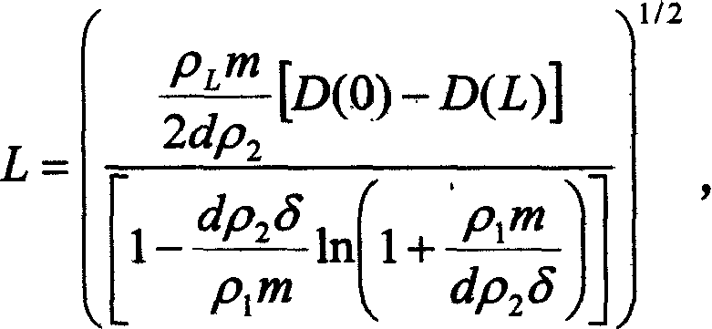
[0007] Specific implementation mode three: Referring to Figures 1 to 3, this embodiment takes the continuous electrodeposition of nickel on the surface of strip-shaped copper foil as an example. The slit 9 on the cover plate 4 enters the through cavity 2, and is derived from the slit 9 on the upper insulating cover plate 3 through the cathode conductive roller 13, wherein: copper foil thickness δ=20 μm, the current lead-in terminal of the anode device is between the cathode and the anode The distance D(0)=30mm, the distance between the cathode and anode at the far end D(L)=10mm, the resistivity of copper ρ Cu =1.63×10 -8 Ω m, resistivity ρ of nickel Ni =20×10 -8 Ω·m, the resistivity ρ of the plating solution L =0.21Ω·m, the density of nickel d=8.9×10 3 kg / m 3 , the amount of electroplated nickel per unit area m = 89 × 10 -3 kg / m 2 (thickness 10 μ m), according to the length L of the through cavity 2, it is obtained by the following formula: L = ...
PUM
| Property | Measurement | Unit |
|---|---|---|
| thickness | aaaaa | aaaaa |
| thickness | aaaaa | aaaaa |
| electrical resistivity | aaaaa | aaaaa |
Abstract
Description
Claims
Application Information
 - R&D
- Intellectual Property
- Life Sciences
- Materials
- Tech Scout
- Unparalleled Data Quality
- Higher Quality Content
- 60% Fewer Hallucinations
Browse by: Latest US Patents, China's latest patents, Technical Efficacy Thesaurus, Application Domain, Technology Topic, Popular Technical Reports.
© 2025 PatSnap. All rights reserved.Legal|Privacy policy|Modern Slavery Act Transparency Statement|Sitemap|About US| Contact US: help@patsnap.com


