Sound heterodyne apparatus and method

A sound wave and sound reflection technology, applied in the direction of sound-generating equipment, binaural systems, stereo systems, etc., can solve problems such as undesired needs

Inactive Publication Date: 2005-07-13
AMERICAN TECH
View PDF1 Cites 11 Cited by
  • Summary
  • Abstract
  • Description
  • Claims
  • Application Information

AI Technical Summary

Problems solved by technology

But the essence of this design is highly undesirable

Method used


Image

  • Sound heterodyne apparatus and method
  • Sound heterodyne apparatus and method
  • Sound heterodyne apparatus and method

Examples


Embodiment Construction

[0061] Referring now to the drawings, in which the various elements of the invention are labeled and in which the invention is discussed to enable those skilled in the art to make and use the invention.

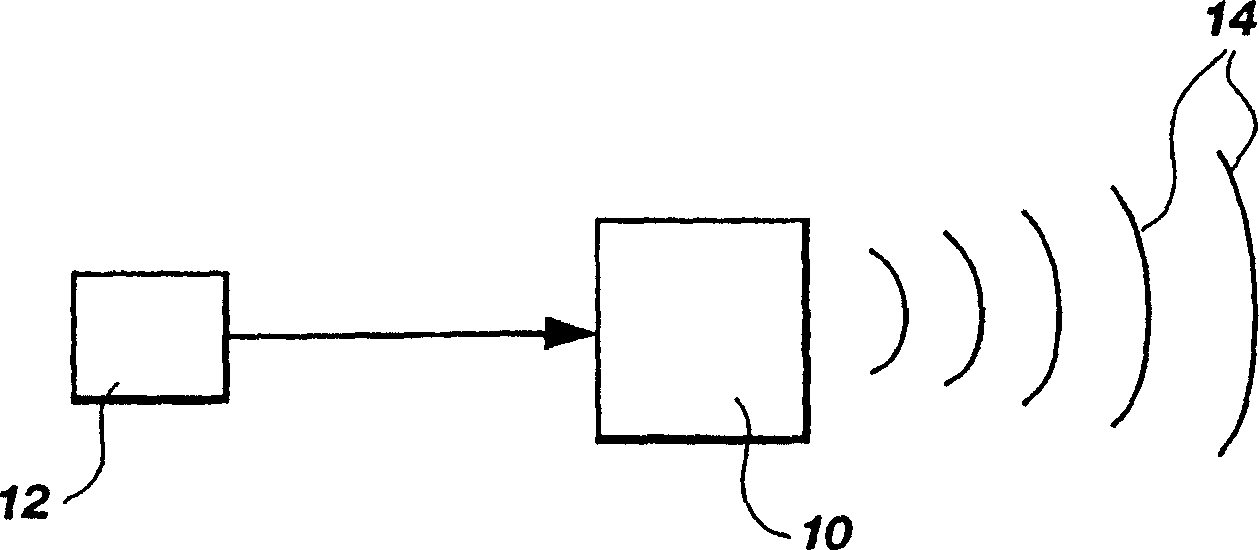
[0062] The present invention departs significantly from the teachings of the current state of the art. Generation of compressional waves is generally considered to be a straightforward process. Think of the direct process as making the radiating element 10 vibrate at the desired frequency, such as figure 1 shown. usually used figure 1 The system directly produces audible and inaudible compression waves above and below the human hearing range. Thus, a conventional compression wave generating system includes a speaker element 10 which may be any dynamic, electrostatic or other direct radiating element, and a signal source 12 such as a signal generator or amplifier. Signal source 12 provides an electrical signal representative of a compression wave having a specific frequenc...


PUM


Abstract

The invention relates to the emission of new acoustic or infrasonic compression waves from a resonant cavity (80) due to the coherence of at least two ultrasonic trains (30, 32). In one embodiment, two ultrasound emitters (20) are directed towards the cavity. When the frequency difference between two ultrasonic wave trains is in the acoustic or infrasonic frequency range, a new sound or infrasonic wave train of this frequency is emitted from the interference cavity or region according to the principle of acoustic heterodyning. The preferred embodiment is a system consisting of a single ultrasound radiating element, which is oriented towards a cavity emitting multiple waves.

Description

[0001] This application is a divisional application of the Chinese Patent Invention Application No. 97196445.9, filed on July 16, 1997, and entitled "Acoustic Heterodyne Apparatus and Method". Technical field: [0002] The present invention relates to the generation of compression waves. In particular, the present invention relates to an apparatus and method for indirect generation of a new type of acoustic or infrasonic compression wave at a new type of compression wave generating source without the use of direct radiating elements. Background technique: [0003] Sound waves are usually the wave-like motion of air or water molecules. Because these media are elastic and generally homogeneous, naturally occurring sound propagates radially from the source in all directions. For example, the sound of an instrument or percussion radiates omnidirectionally in a unified and complete form, carrying octaves, overtones, and a full range of dynamics, which together provide the instan...

Claims


Application Information

Patent Timeline
Patent Type & Authority Applications(China)
IPC IPC(8): H04R23/00G10K15/02H04B11/00H04R3/00H04R3/02H04R5/02H04S1/00
CPCG10K15/02H04B11/00H04R3/02H04R5/02H04R23/00H04R2217/03H04S1/002H04R3/00
Inventor 埃尔伍德·G.·诺里斯
Owner AMERICAN TECH
Why Eureka
Try Eureka