Test table of automobile braking ABS based on brake inertia test

A technology of automobile braking and test bench, which is applied in the direction of measuring devices, machine/structural component testing, instruments, etc. It can solve the problems of high cost, different braking strength, and the inability to simulate the ABS performance test of cars, etc., so as to improve the utilization rate Effect

Inactive Publication Date: 2005-08-03
BEIJING INSTITUTE OF TECHNOLOGYGY +1
View PDF0 Cites 27 Cited by
  • Summary
  • Abstract
  • Description
  • Claims
  • Application Information

AI Technical Summary

Problems solved by technology

[0011] 1) The performance of the mechanical unit and the performance of the hydraulic unit in the automotive ABS device are not tested, there are tests that are not oriented to the overall ABS device, and the performance of the ABS device cannot be fully tested;
[0012] 2) It is impossible to fully test the performance matching of the ABS electronic control unit, mechanical unit and hydraulic unit;
[0013] 3) When testing the data acquisition software in the electronic control unit, the input signal of the electronic control unit is the wheel speed signal generated by the instrument, which is very different from the wheel speed signal collected during the actual vehicle operation, so it cannot be comprehensively analyzed Test the Rationality of Data Acquisition Software Design in Electronic Control Unit
[0023] 3) It is still difficult to establish an accurate vehicle dynamics model. The accuracy of the establishment of the vehicle dynamics model determines the accuracy of the ABS performance test. For example, the tire model and suspension system model in the existing vehicle model cannot meet the requirements of accurate modeling. Therefore, there is a certain error between the performance test of ABS and the performance test of real vehicle ABS by semi-physical simulation method;
[0024] 4) There is a certain difference between the simulation of the vehicle braking process and the real vehicle road braking process, and it cannot replace the real vehicle ABS performance test
[0033] 1) Due to the limitations of the motor power and transmission belt of this type of test bench, the maximum speed that can be tested is low, and the high-speed performance assessment of the ABS device cannot be realized, which is not enough for the performance assessment of the ABS device;
[0034] 2) Due to the limitation of the belt transmission device, the wheelbase range of the test vehicle adapted to the test bench is 2.35 ~ 2.85m, which can only be adapted to the test of the car. For other light passenger cars and trucks, the wheelbase range cannot meet the requirements; for For other medium-sized and heavy-duty vehicles, the load-carrying capacity, number and arrangement of rollers, and the applicable wheelbase range of this type of test bench cannot meet the requirements;
[0035] 3) The moments of inertia of the four inertial flywheels are fixed, which cannot meet the performance test requirements of ABS devices of cars with different vehicle qualities;
[0036] 4) Different types of cars have different drive types, different center of mass heights, different bridge loads, and different braking strengths. Therefore, the proportions of dynamic normal loads on the front and rear axles are different during braking. The proportion of normal loads on the test bench is fixed and cannot ABS performance test of a car that simulates different dynamic normal loads on the front and rear axles;
[0037] 5) For roads with uniform adhesion, only dry and wet roads can be simulated, and low-adhesion roads such as snowy roads and icy roads cannot be simulated;
[0038] 6) For split roads, only dry road-wet road conditions can be simulated, and the high / low adhesion coefficients of the roads on both sides are very close, which cannot reflect the control performance of ABS on split roads;
[0052] 1) Only a simple evaluation of the assembly effect of the ABS device can be carried out, and the performance of the ABS device cannot be fully tested;
[0053] 2) It cannot be used for performance research and development of ABS devices;
[0054] 3) There are many auxiliary devices on the test bench;
[0055] 4) Higher cost

Method used


Image

  • Test table of automobile braking ABS based on brake inertia test
  • Test table of automobile braking ABS based on brake inertia test
  • Test table of automobile braking ABS based on brake inertia test

Examples


Embodiment Construction

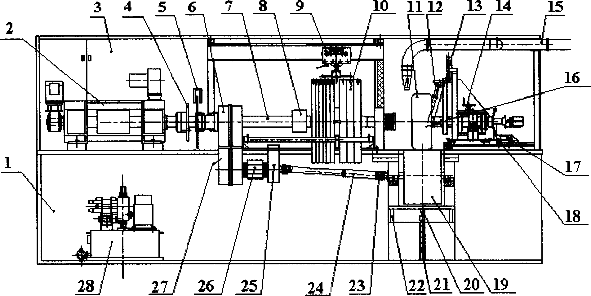
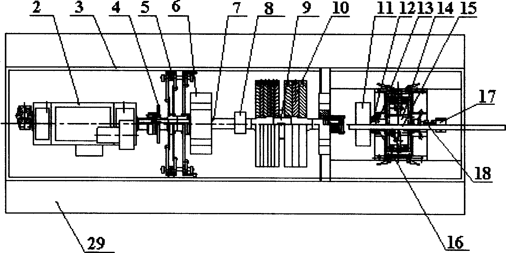
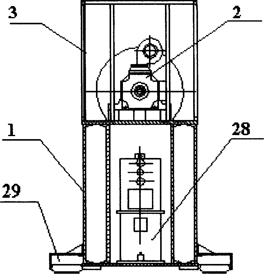
[0101] exist figure 1 , figure 2 and image 3 In the process, before the ABS performance test or the brake routine performance test, the wheel torque sensor (16) and the roller torque sensor (26) are calibrated by the static torque calibration mechanism (8), and the spindle speed is calibrated by an external standard tachometer. The sensor (4) and the wheel speed sensor (13) perform speed calibration, and the external standard pressure sensor performs pressure calibration on the lateral force sensor (18) and positive pressure sensor (20). After each sensor is calibrated and calibrated, it can be carried out Automotive ABS performance test or brake routine performance test.

[0102] exist figure 1 , figure 2 and image 3 Among them, when carrying out the ABS performance test, push the gear shift handle (27) of the gear box through the clutch / coupling oil cylinder of the gear box so that the sliding gear of the II shaft of the gear box (6) is in the combined position, so ...


PUM


Abstract

The automobile braking ABS test table mainly a includes drive motor and its control mechanism, a main shaft, an inertial flywheel and its hanging mechanism, a skid platform, a gear box and gimbal, a roller and guide rail, a tested wheel-roller normal pressure loading unit and a regulating mechanism, a tested wheel-roller side pressure loading unit and a regulating mechanism, a wheel cylinder braking pressure switching mechanism, a speed and force sensing unit, a hydraulic pump station, a temperature regulator, an emergency brake, a control cabinet, a data recording, a processing, displaying and printing unit and frame and a protecting hood. During ABS test, the main driving motor drives the driving box, the gimbal and the driving shaft through the main shaft to drive the roller, the roller drives the wheels and the main shaft also drives the flywheel. In conventional brake performance test, the main driving motor drives the flywheel and the brake only via the main shaft.

Description

Technical field [0001] The invention relates to an automobile brake anti-lock braking device test bench, in particular to an automobile brake anti-lock brake device experimental bench (abbreviated as an ABS experimental bench) based on a brake inertia test. Background technique [0002] At present, the existing domestic and foreign manufacturers of inertial test benches for automobile brakes include American Link Company and Greening Company, German Schenck Company, and Jilin University Non-Mine Technology Equipment Research Institute. Automobile brake inertia test bench is used for performance testing and research of automobile brake products, and can carry out all routine performance tests of automobile brakes. [0003] At present, the technical status of domestic ABS test benches is zero, and the existing foreign automobile ABS test benches can be divided into four categories: [0004] One is the experimental bench limited to performance testing of the electronic and ele...

Claims


Application Information

Patent Timeline
Patent Type & Authority Applications(China)
IPC IPC(8): G01M17/007
Inventor 刘昭度曲波崔海峰赵继昌齐志权马岳峰边立舰
Owner BEIJING INSTITUTE OF TECHNOLOGYGY
Why Eureka
Try Eureka