Laser feedback nano displaycement measuring device

A technology of laser feedback and displacement measurement, which is applied in the field of laser measurement, can solve problems such as instability, difficulty in measurement, and limitation of displacement measurement resolution, and achieve the effects of simple device, convenient implementation, and low price

Inactive Publication Date: 2005-08-03
TSINGHUA UNIV
View PDF0 Cites 23 Cited by
  • Summary
  • Abstract
  • Description
  • Claims
  • Application Information

AI Technical Summary

Problems solved by technology

However, using this method to determine the direction will limit the resolution of displacement measurement, because a complete cycle must be used to determine the tilt direction of the waveform, so the displacement of less than half the wavelength is half the wavelength of the He-Ne laser of 632.8 na

Method used


Image

  • Laser feedback nano displaycement measuring device
  • Laser feedback nano displaycement measuring device
  • Laser feedback nano displaycement measuring device

Examples


example 1

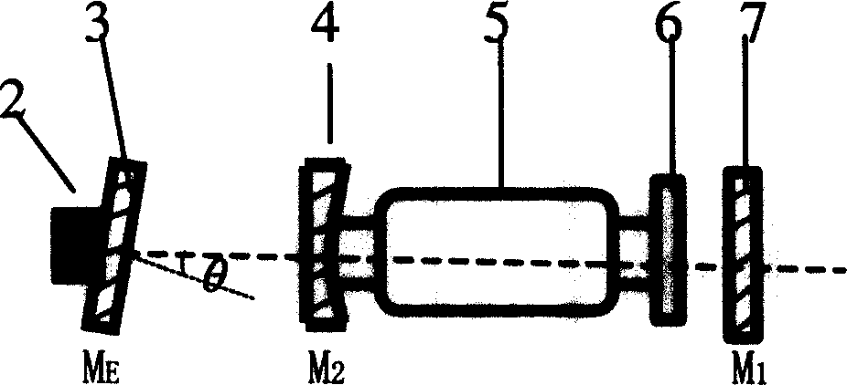
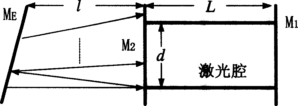
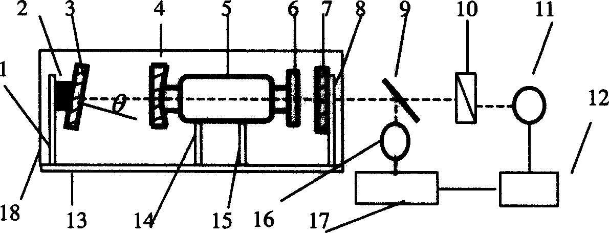
[0076] The schematic diagram of the experimental device is as image 3 shown. image 3 Middle: The half-external-cavity laser is composed of a gain tube 5, a second reflector 4, and a first reflector 7. The gain tube 5 is filled with a mixed gas of He and Ne with a ratio of 7:1. One end of the gain tube is fixed with an antireflection window 6 . The resonant cavity is composed of a first reflector 7 and a second reflector 4, and the reflection coefficients are r 1 = 0.999 and r 2 =0.994, they constitute the inner cavity of the laser; 3 is the laser feedback external cavity mirror, the reflection coefficient is r 3 , it forms the laser feedback external cavity with the second reflector 4, and the length of the laser feedback external cavity is l. The initial cavity length of the laser feedback external cavity is l=190mm. The angle θ=40μrad between the surface normal of the external cavity feedback mirror 3 and the laser beam; 9 is the beam splitter BS; 10 is a polarizer, w...

example 2

[0079] The schematic diagram of the experimental setup is still as image 3 shown. Just shorten the initial distance between the feedback mirror and the laser to make l=30mm. The experimental results at this time are as Figure 6 Shown, where (b) is the time axis expanded waveform of (a). The 1# curve in the figure is the voltage applied to the PZT, and the 2# curve is the laser intensity output by the first photodetector 16 . The fluctuation frequency of the laser intensity at this time is 40 times that of the traditional self-mixing interference, that is, one cycle of the laser intensity fluctuation corresponds to the change of the external cavity length λ / 80, because the wavelength of the laser is 632.8nm, so the resolution of the displacement measurement is 8nm. The recognition of the moving direction of the measured object is the same as the example 1.

[0080] The measurement system composed of all-cavity lasers is used, and the experimental device is as Figure 4 A...


PUM


Abstract

The present invention belongs to the field of laser measurement technology, and features that 632.8 nm He-Ne laser and outer high reflectivity reflector constitute one non-collimated multiple laser feedback system. The outer reflector is fixed onto the tested object, and when the tested object is shifted, the laser strength fluctuation frequency may reach several to decades times that of the traditional feedback mode to result in high order frequency multiplying effect in laser strength fluctuation. The laser strength fluctuation period corresponds to nanometer level change in the distance between the outer reflector and the laser, so that measuring the period number of the laser strength variation can obtain the displacement of the measured object. When the object changes its moving direction, the laser polarization state jumps between two orthogonal directions and this may be used in judging the moving direction of the object.

Description

technical field [0001] The invention belongs to the technical field of laser measurement. Background technique [0002] The current laser technology has been successfully used for high-precision measurement of many physical and geometric quantities. The commonly used measurement method is to use the interference phenomenon of laser, that is, laser interferometer. The basic principle is to divide the beam output by the laser into two beams, one beam is the measuring beam; the other beam is the reference beam, when the measured object is displaced, the interference fringes of the two beams will move, and the interference fringes will be recorded. The number of moves can be converted into a displacement change. Every movement of an interference fringe corresponds to the displacement of half the light wavelength of the measured object. When using a 632.8nm He-Ne laser light source, the resolution of displacement measurement is 316.8nm. In order to improve the measurement reso...

Claims


Application Information

Patent Timeline
IPC IPC(8): G01B11/00G01S11/12G01S17/06
Inventor 张书练费立刚
Owner TSINGHUA UNIV
Why Eureka
Try Eureka