

Synchronous bus controller of step scanning projection photo etching machine and synchronous control system
A technology of step-scan and synchronous bus, which is applied in transmission system, digital transmission system, microlithography exposure equipment, etc.
- Summary
- Abstract
- Description
- Claims
- Application Information
AI Technical Summary
Problems solved by technology
Method used
Image

Examples
Embodiment Construction
[0038] The synchronous bus controller is the core controller of the synchronous control of the step-scan projection lithography machine. After all subsystems participating in the synchronous scanning process are negotiated under the exposure control software, the synchronous bus controller implements real-time synchronous control on the hardware of the entire scanning process.
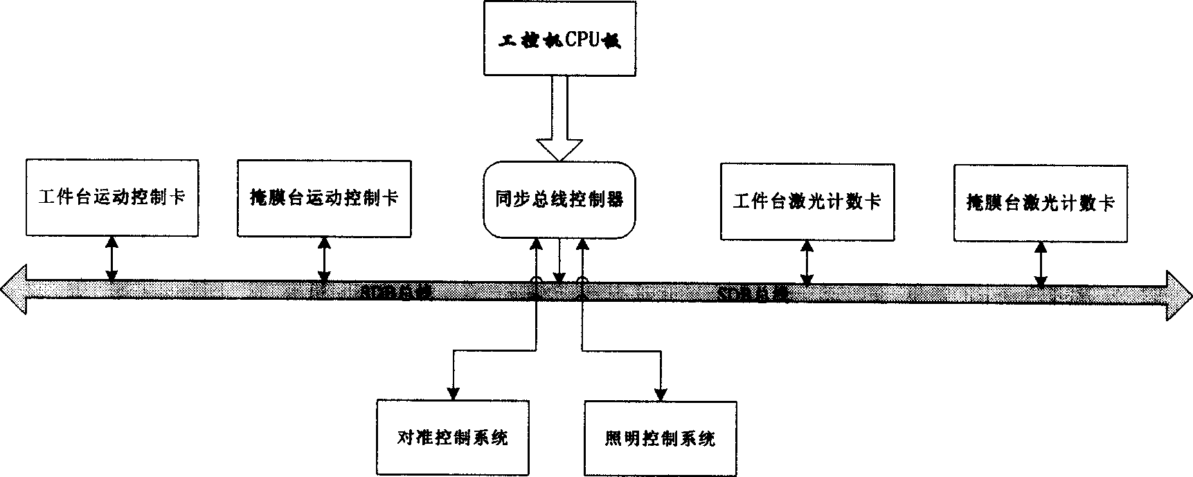
[0039] The structural block diagram of the synchronous control process is as follows: figure 2 As shown, the synchronous bus controller is the core of the real-time synchronous control process, providing a unified time reference for all sub-modules and motion control cards involved in scanning exposure. The exposure control software transmits the scanning parameters to the synchronous bus controller through the VME bus interface of the CPU board of the industrial computer, and the synchronous bus controller controls the workpiece table motion control card, mask table motion control card, workpiece Th...
PUM
 Abstract
Description
Claims
Application Information