
Substrate processing device and substrate processing method

A technology for a substrate processing device and a substrate processing method, which is applied in the directions of transportation and packaging, ion implantation and plating, lighting and heating equipment, etc., can solve the problems of uneven brightness, mixed crystal planes, and insufficient for high-precision large-scale PDP, etc. Achieve the effect of reducing film peeling

Active Publication Date: 2005-08-03
ANELVA CORP
View PDF2 Cites 31 Cited by
  • Summary
  • Abstract
  • Description
  • Claims
  • Application Information

AI Technical Summary

Problems solved by technology

In the research, it was found that an evaporation device has been developed. The structure of the device is to cover the carrier with a shield when the film is formed to prevent the film from adhering to the carrier, and the shield is not taken out but left in the vacuum chamber ( Japanese Patent Laid-Open Publication No. 11-131232), this device and Figure 7 Compared with the device structure shown, although it has been improved, it is still not enough to support high-precision, high-performance large-scale PDPs
For example, if the opening of the shield is larger than the opening of the carrier, the thin film will adhere to the carrier, causing the same problem as above, while if the opening of the shield is small, the evaporation material will flow to the outer periphery of the substrate and accumulate, resulting in The film thickness is thin and the crystal planes are mixed, resulting in the problem of uneven brightness

Method used


Image

  • Substrate processing device and substrate processing method
  • Substrate processing device and substrate processing method
  • Substrate processing device and substrate processing method

Examples


Embodiment Construction

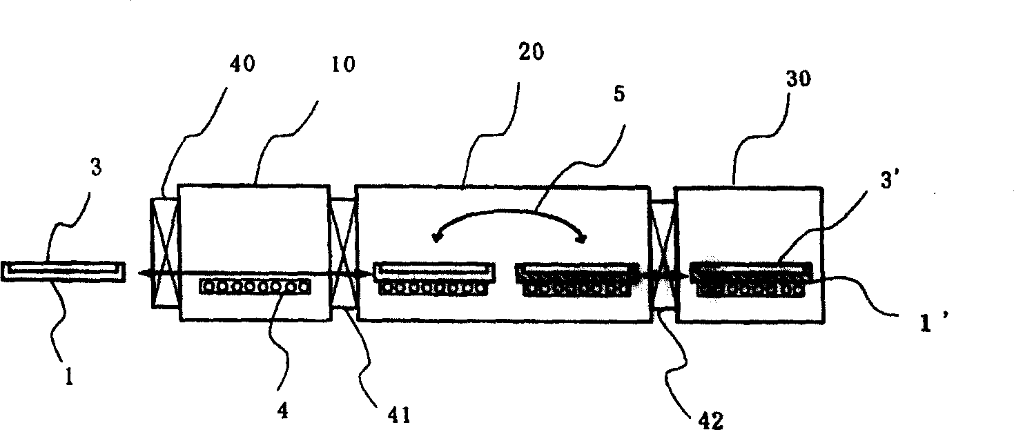
[0047] figure 1 A schematic diagram showing the basic structure of the substrate processing apparatus of the present invention.

[0048] Such as figure 1 As shown, the substrate processing apparatus has a structure in which the load-lock vacuum chamber 10, the substrate transfer chamber 20, and the processing chamber 30 are connected by gate valves 41 and 42, so that the first carrier 1 can be moved between the load-lock vacuum chamber 10 and the processing chamber 30. The substrate is transferred between the substrate transfer chambers 20 , and the second carrier 1 ′ can be moved between the substrate transfer chamber 20 and the processing chamber 30 to transfer the substrate. Here, the substrate transfer chamber 20 is maintained at a temperature such as N 2 Gas or other dry gas environment or vacuum state, and a substrate transfer mechanism 5 is installed.

[0049] In the atmosphere, the substrate 3 is loaded on the first carrier 1, carried into the load-lock vacuum cha...


PUM


Abstract

A substrate processing device and a substrate processing method for general purpose capable of suppressing the contamination of atmosphere in a processing chamber through carriers, continuously performing a stable conveyance and a high quality substrate processing, and coping with further upsizing substrates and various substrate dimensions, the device comprising a load lock chamber allowing the carriers having the substrate mounted thereon to be carried therein, a substrate transfer chamber having a transfer mechanism for transferring the substrate between the carriers, and a substrate processing chamber for applying a specified processing to the substrate, characterized in that the first carrier moves between the load lock chamber and the substrate transfer chamber and the second carrier moves between the substrate transfer chamber and the substrate processing chamber, and the substrate is transferred between the first carrier and the second carrier by the transfer mechanism.

Description

technical field [0001] The present invention relates to a substrate processing apparatus and processing method, which continuously transports a carrier loaded with a substrate to a processing chamber and performs predetermined processing, and particularly relates to processing that can solve the problem caused by the movement of the carrier between the processing chamber and the atmosphere The problem of contamination of the chamber environment can be avoided, and the formation of high-quality thin films and etching can be performed stably. Background technique [0002] As a known example of a substrate processing apparatus, for Figure 7 The production is illustrated with a vapor deposition apparatus for illustration. Such as Figure 7 As shown, in the known vapor deposition apparatus, a load-lock vacuum chamber (Lo-Dock) 10 for carrying in a carrier, a heating chamber 70, a vapor deposition chamber 30, a load-lock vacuum chamber 10' for carrying out a carrier, etc. , are ...

Claims


Application Information

Patent Timeline
IPC IPC(8): C23C14/56H01L21/00
CPCH01L21/67748C23C14/56H01L21/67173B65G49/07H01L21/68
Inventor 中河原均井川诚一畦原吉史
Owner ANELVA CORP
Learn More