
Plane glass ceramic object having at least one dull polishing region and its preparing method

A glass-ceramic, frosted technology, applied in glass manufacturing equipment, glass forming, heating methods, etc., can solve the problem that the coating is only suitable for holding, and achieve the effect of a simple process

Active Publication Date: 2005-08-17
SCHOTT AG
View PDF12 Cites 11 Cited by
  • Summary
  • Abstract
  • Description
  • Claims
  • Application Information

AI Technical Summary

Problems solved by technology

But the heat resistance of this type of resin is up to 400°C, so that the coating is only suitable for areas of the glass-ceramic cooking surface that are kept in cold operation (below 400°C)

Method used


Image

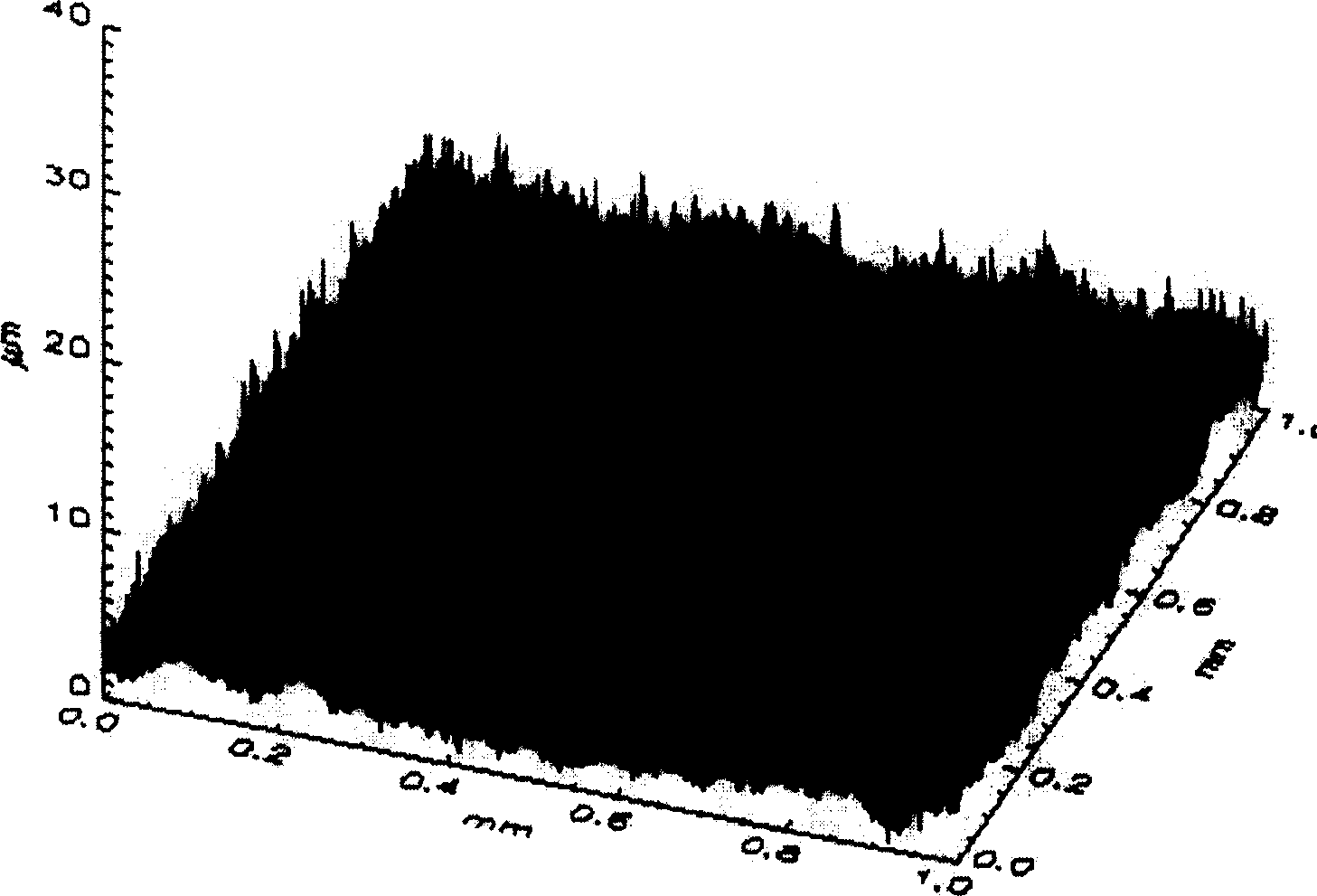
  • Plane glass ceramic object having at least one dull polishing region and its preparing method
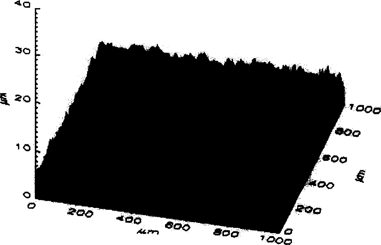
  • Plane glass ceramic object having at least one dull polishing region and its preparing method
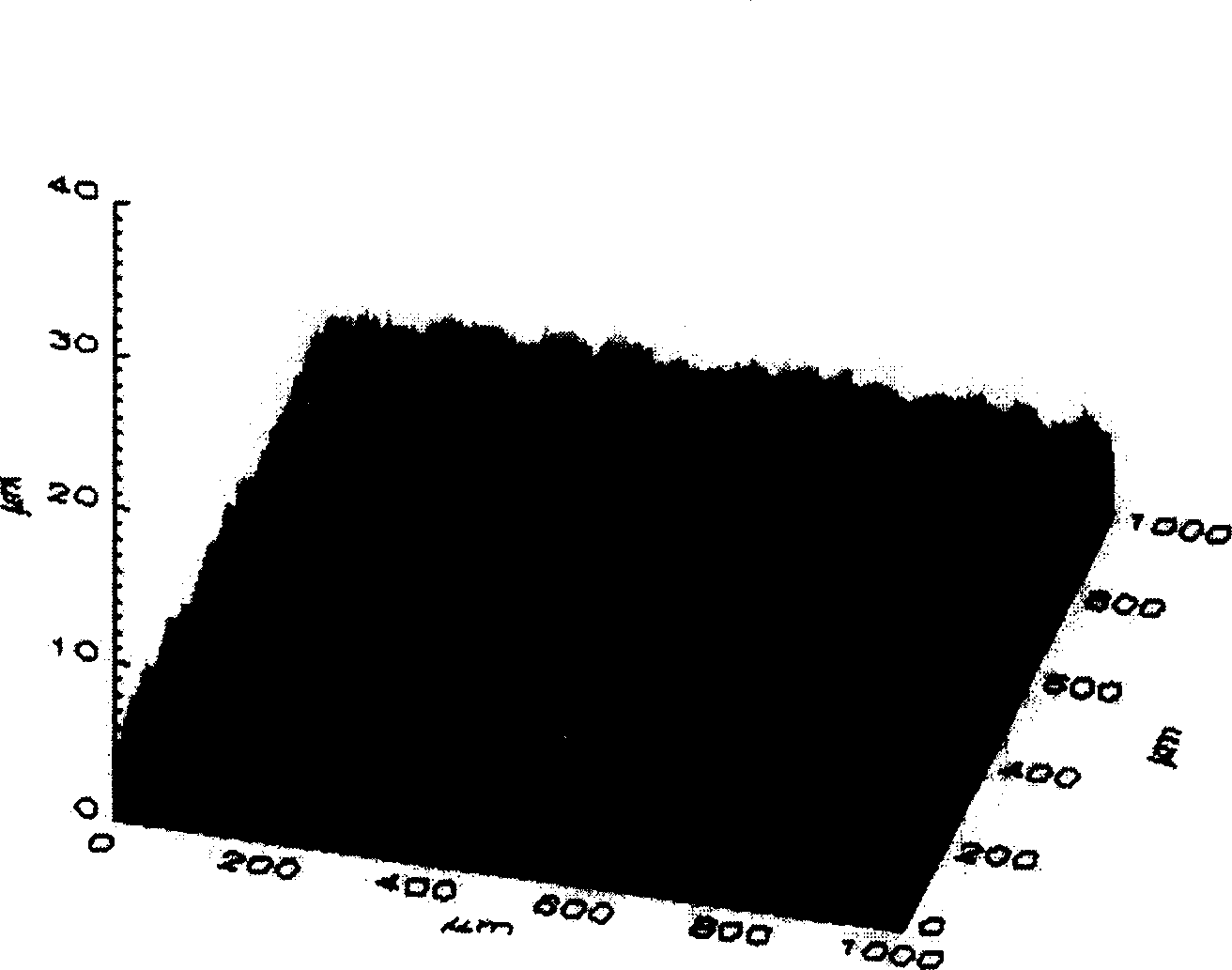
  • Plane glass ceramic object having at least one dull polishing region and its preparing method

Examples


Embodiment

[0033] Black glass-ceramic (designation CERANHIGHTRANS) described in DE 19721737 C1  , and described in EP 0220333 B1) on plate-like substrates in a non-ceramic state, ie in the corresponding blank glass matrix, are screen-printed by a usual screen-printing medium based on aromatic hydrocarbon mixtures ( Such as Zschimmer&Schwarz GmbH & Co.KG Chemische Fabriken products) and the grade is BOROFLOAT  3.3 Paste composed of borosilicate glass. The paste ratio is 10 parts by weight of glass frit and 12 parts by weight of screen printing medium. The mesh of the screen was 36 μm.

[0034] The data of glass powder are as follows:

[0035] Oxide

Weight % (±0.3)

SiO 2

80.9

B 2 o 3

12.8

Na 2 o

3.3

K 2 o

0.6

Al 2 o 3

2.4

[0036] Clarifying agent: NaCl

[0037] Granularity

pulp

powder

D10[μm]

0.4

0.4

D50[μm]

0.9

0.9

D99[μm]

2.6

...


PUM


Abstract

A flat glass-ceramic component comprises a matt area formed by a coating of glass on the glass-ceramic. The glass has a softening point in excess of 750oC and a different refractive index to that of the glass-ceramic. The glass is a borosilicate glass with a softening point between 750 and 850oC. The glass coating is applied by sieve printing.

Description

technical field [0001] The invention relates to a planar glass-ceramic body having at least one frosted region, preferably a glass-ceramic body for use as a cooking surface. However, the planar glass-ceramic body can also be formed by sight glass panes, such as chimney sight glass panes or furnace sight glass panes, as well as by lamp shades. [0002] The invention also relates to a method for producing such glass-ceramic bodies. Background technique [0003] New cooking zones usually have glass-ceramic cooking surfaces for the individual cooking zones or cooking positions heated by gas, induction radiators or electric radiators. [0004] Known glass-ceramic cooking surfaces generally have a dark to black color appearance, in particular to ensure the desired invisibility into the cooking area interior. This can be achieved by coloring the glass-ceramic raw material in the melt or by an opaque colored coating of the underside of the corresponding glass-ceramic plate. [00...

Claims


Application Information

Patent Timeline
IPC IPC(8): F24C15/04A47J27/00C03B19/01C03C4/00C03C8/02C03C10/00C03C17/02C03C17/04C04B41/86F24C15/06F24C15/10H05B3/74
CPCC03C17/04H05B3/748
Inventor I・科斯马斯D・温内曼恩L・亚亚比H・斯特里格勒
Owner SCHOTT AG
Learn More