System and method for testing three-dimensional motion of microstructure by image matching and phase shift interference

A technology of three-dimensional motion and phase-shift interference, which is applied to measurement devices, optical devices, instruments, etc., can solve problems such as difficulty in three-dimensional topography, inability to extract plane motion parameters of image edge information, and inability to obtain three-dimensional topography. The effect of the test

Inactive Publication Date: 2005-08-17
TIANJIN UNIV
View PDF0 Cites 14 Cited by
  • Summary
  • Abstract
  • Description
  • Claims
  • Application Information

AI Technical Summary

Problems solved by technology

Through the comprehensive analysis and comparison of the existing technologies, the technical solutions reported at present mainly have the following problems in practical application: (1) The size range of the microstructure in the MEMS device can reach tens or even hundreds The measurement range of the phase-shift interference method is generally only a few microns from the surface, so the interference fringes can only be formed in a certain area under the entire field of view, that is, the three-dimensional morphology of the microstructure under the entire field of view cannot be obtained; (2 ) Although most of the moving microstructures have off-plane geometric dimensions and motion amplitudes in the range of a few microns, the working distance can be adjusted to make the surface of the moving microstructures form interference fringes, and the edge where the interference fringes disappear generally contains plane motion information, but When using the phase-shifting interferometry method, phase extraction and phase unwrapping steps need to be carried out successively. The edge interference data will easily lead to the failure of the three-dimensional shape extraction. Generally, it is necessary to artificially select the area inside the edge for interference fringe processing. The image edge information The loss of plane motion parameters will make it impossible to extract the plane motion parameters, which will make it difficult to establish the motion measurement coordinate system, and the extraction of out-of-plane motion information will also cause errors; (3) the accuracy of extracting plane motion information using 3D topography is low, which mainly It is difficult to use the sub-pixel technology for the obtained three-dimensional shape, and the measurement accuracy of the plane motion parameters can only reach the pixel level

Method used


Image

  • System and method for testing three-dimensional motion of microstructure by image matching and phase shift interference
  • System and method for testing three-dimensional motion of microstructure by image matching and phase shift interference
  • System and method for testing three-dimensional motion of microstructure by image matching and phase shift interference

Examples


Embodiment 1

[0027] This embodiment mainly focuses on testing the planar motion parameters of the microresonator and establishing a relative coordinate system for accurate extraction of out-of-plane motion parameters using image matching technology under white light strobe lighting conditions.

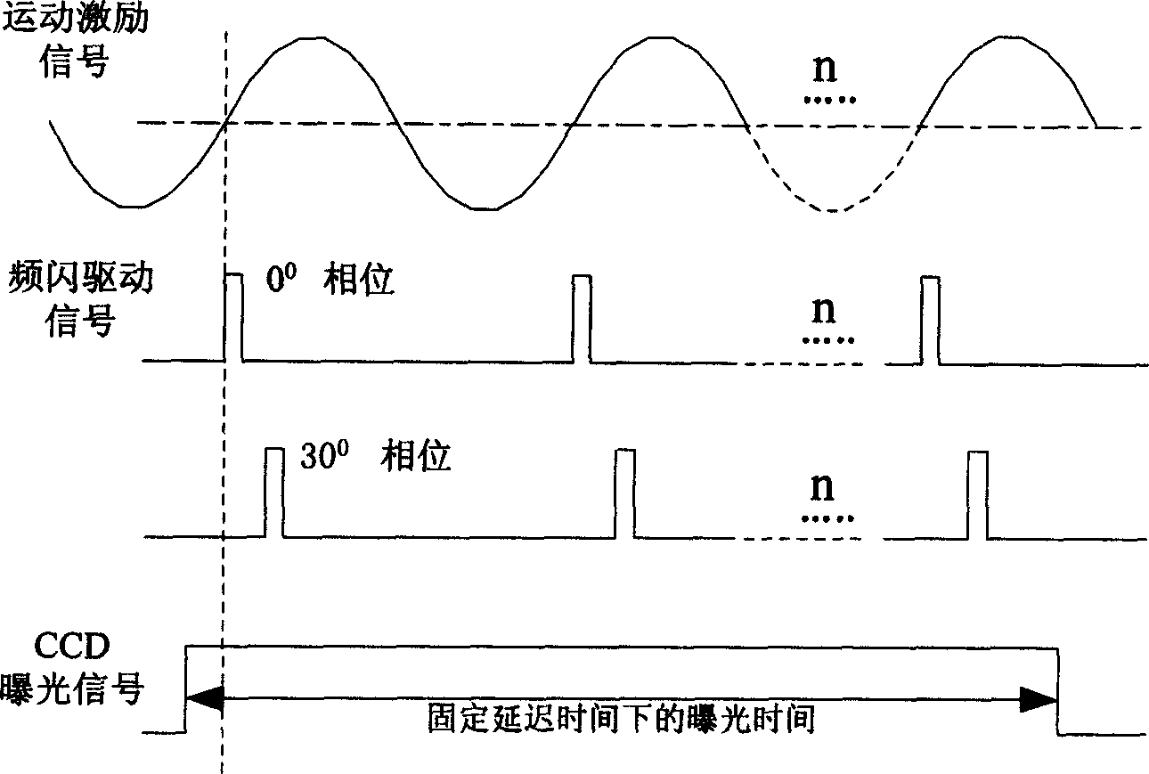
[0028] The signal sequence of the stroboscopic lighting to realize the measurement of high-frequency motion parameters is as follows: figure 1 As shown, the delay time of the two signals is controlled by the measurement and control computer, and the figure only lists the delay of the two signals during the acquisition of the motion image of the 0° and 30° motion phase plane. The motion excitation signal is a periodic sinusoidal signal, and the strobe drive signal is a positive pulse with a width of about 1 microsecond, which appears at a specific phase of each cycle and repeats 1000 times. The CCD camera collects images under the field of view of the optical microscope , the exposure time is the to...

Embodiment 2

[0032] This embodiment mainly focuses on the condition of monochromatic light stroboscopic illumination. After the relative position of the corresponding point in the microresonator under test in the field of view of the optical microscope is determined in Embodiment 1, the microresonator separation is carried out using phase shift interference technology. Accurate extraction of surface motion parameters.

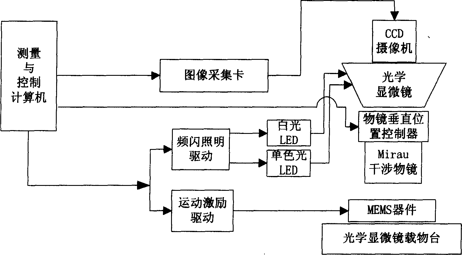
[0033] In this embodiment, the signal sequence of stroboscopic lighting to realize the measurement of high-frequency motion parameters is still as follows: figure 1 shown. figure 2 It is a test system for the three-dimensional motion parameters of microstructures in microelectromechanical systems (MEMS) using image matching and phase shifting interferometry. In this embodiment, the white light LED does not work, the monochromatic light LED works, and the objective lens vertical position controller works.

[0034] In this embodiment, the test device, motion excitation sig...


PUM


Abstract

This invention discloses a system and a method for testing microstructure 3-D motion with image-match and phase shift interference. The system includes an optical microscope, a Mirau interference object glass, its vertical position controller, a strobe lighting driving device, a CCD camera, image collecting cards, a numeric computer and a motion excitation driver, among which, the strobe lighting device drives LEDS of white light and monochromatic light to irradiate the micro structure, which tests the plane motion parameter in white light LED irradiation and tests its out-of -plane motion parameter in monochromatic light LED irradiation. The method includes synchronous control to strobe and drive signals, extraction of plane motion parameter in white light irradiation, set up a relative coordinate system, the obtaining of the surface shape and the extraction coordinate system.

Description

technical field [0001] The invention relates to a method and system for testing three-dimensional motion parameters of microstructures in microelectromechanical systems (MEMS) using image matching and phase shifting interference techniques comprehensively. It belongs to the mechanical quantity measurement technology of the photoelectric non-contact method for micro-electromechanical systems. Background technique [0002] Micro-Electro-Mechanical Systems (MEMS) is developed on the basis of microelectronics technology. It is an integrated device or system composed of electronic and mechanical components. It is manufactured by a mass-processing process compatible with integrated circuits. At the same time, computing, sensing and execution are integrated, thus changing the way of perceiving and controlling the natural world. Most of the manufacturing processes of microelectromechanical systems (MEMS) are compatible with the processing technol...

Claims


Application Information

Patent Timeline
Patent Type & Authority Applications(China)
IPC IPC(8): G01B11/00G01B11/25
Inventor 胡晓东栗大超胡春光郭彤陈津平胡小唐
Owner TIANJIN UNIV
Why Eureka
Try Eureka