Eureka AIR delivers breakthrough ideas for toughest innovation challenges, trusted by R&D personnel around the world.

Wide viewing field and high resolution ratio imaging arrangement for pushbroom optical spectrum imagers

A high-resolution, wide-field-of-view technology, applied in spectrometry/spectrophotometry/monochromators, instruments, scientific instruments, etc., can solve spatial registration errors between images, low operating efficiency, and enlarged images Deal with difficulty and other issues to achieve the effects of flexibility and practicability, reduce the workload of installation and calibration, improve operation efficiency and scope of application

Inactive Publication Date: 2005-09-07
SHANGHAI INST OF TECHNICAL PHYSICS - CHINESE ACAD OF SCI +1
View PDF0 Cites 9 Cited by
  • Summary
  • Abstract
  • Description
  • Claims
  • Application Information

AI Technical Summary

Problems solved by technology

Due to the limitation of optical efficiency and the difficulty of manufacturing large area array detectors for frame transfer, the field of view of the single imaging spectrometer currently existing in the world is not greater than 40°, so the operating efficiency is low, and at the same time, it cannot meet the growing demand for high High-resolution hyperspectral images (high-resolution hyperspectral images can not only provide fine geometric characteristics of ground targets, but also provide rich spectral information, and have great practical value for automatic and rapid target recognition and classification of ground objects), These have greatly limited the scope of use of hyperspectral imagers
Currently, multiple independent small-field-of-view imaging spectrometers usually use field-of-view splicing to realize wide-field imaging. The installation and calibration requirements are extremely high, which also increases the difficulty of image processing
At the same time, the high-resolution images and spectral images of the same ground feature obtained by different instruments are used for image registration and image fusion to generate new high-resolution hyperspectral images. Due to the inevitable gap between the optical heads of the operating instruments There is a difference in performance, which will not only lead to difficulties in data fusion processing, but also the error of spatial registration between images has a great impact on the effect of image fusion

Method used

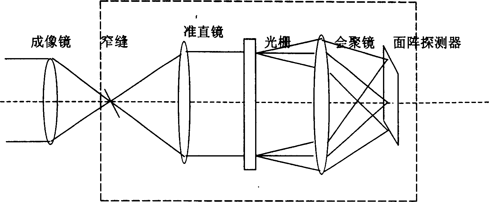

Image

  • Wide viewing field and high resolution ratio imaging arrangement for pushbroom optical spectrum imagers
  • Wide viewing field and high resolution ratio imaging arrangement for pushbroom optical spectrum imagers
  • Wide viewing field and high resolution ratio imaging arrangement for pushbroom optical spectrum imagers

Examples


Embodiment Construction

[0025] Combine below Figure 2 ~ Figure 3 A preferred embodiment of the present invention is given, and the features of the present invention are mainly described in further detail, rather than being used to limit the scope of the present invention:

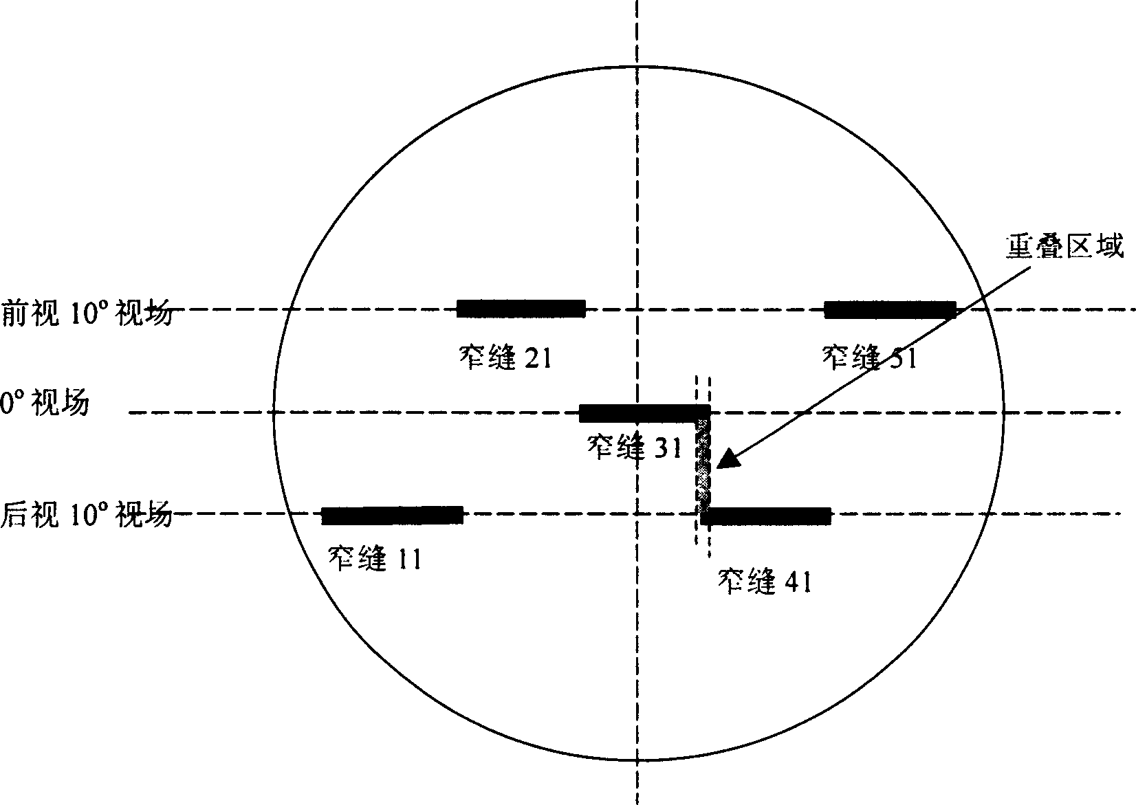
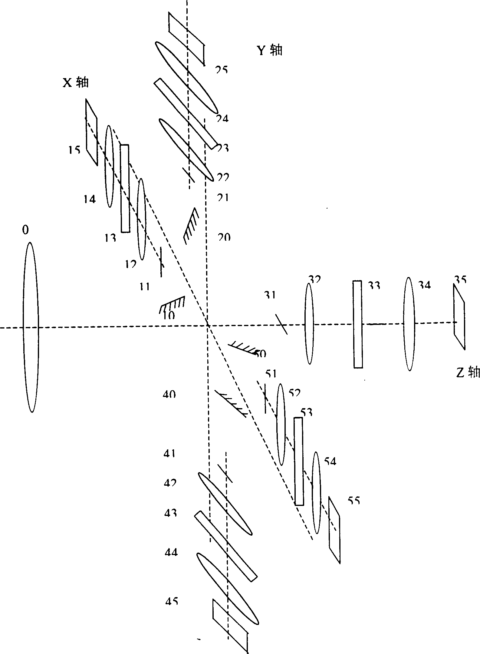
[0026] see first image 3 , image 3 It is a structural schematic diagram of the optical head module of an 80° field of view pushbroom hyperspectral imager according to a specific embodiment of the present invention. The field of view of the imaging mirror 0 is 90°, and the focal length is 20mm. When not adding four turning mirrors 10, 20, 40, 50, five slits 11, 21, 31, 41, 51 at the focal plane of the imaging lens are as figure 2 As shown in the distribution, slits 11 and 41 are placed at 10° rear view along the track, slit 31 is placed at 0° field of view along the track, slits 21 and 51 are placed at 10° front view along the track, and the length of the slits is 7mm, spliced ​​into a 34mm long narrow slit in the rail pass...


PUM


Abstract

A wide viewing field and high-definition imaging structure of frayed end imaging spectrograph, which comprises wide viewing field image-forming lens, several narrow slits, spectrometer, which comprises collimating mirror, optical grating and collective lens), and plate array light-sensitive detector. Optic axis of spectrometer is parallel with imaging lens optic axis. Light splitting is exerted on different viewing narrow slits of image lens focal surface to paste-up a wide viewing field and high-definition imaging spectrum system. According to actual requirement, length and sum of narrow slit, focus of imaging lens and the size of detecting element can be chosen to produce imaging spectrograph of different imaging viewing fields and distinguishabilities.

Description

Technical field: [0001] The invention relates to an improved structure for realizing wide field of view and high resolution of a hyperspectral imager, in particular to a wide field of view and high resolution imaging structure of a spaceborne / airborne pushbroom type hyperspectral imager. Background technique: [0002] Imaging spectrometer is a new generation of remote sensing instrument developed with the needs of earth observation and the progress of optoelectronic technology in recent years. It organically combines traditional two-dimensional imaging remote sensing technology At the same time as spatial information, the spectral image of the target is acquired with high spectral resolution. Since the obtained spectral image data contains spectral information related to the components of the observed target, it can reveal the spectral characteristics, existence and material composition of the surface object, thus making it possible to directly identify the imaging target. T...

Claims


Application Information

Patent Timeline
IPC IPC(8): G01J3/02G01S7/481G01S17/89G02B7/00
Inventor 王建宇何志平舒嵘薛永祺方抗美
Owner SHANGHAI INST OF TECHNICAL PHYSICS - CHINESE ACAD OF SCI
Why Eureka
Eureka Blog
Learn More