
Determining method of vortex street mass flow

A mass flow and detection method technology, applied to mass flow measurement devices, indirect mass flow meters, volume/mass flow generated by mechanical effects, etc., can solve the problems of measurement accuracy influence, large structure, large measurement system structure, etc., to achieve The method is simple and easy, the measurement accuracy is high, and the effect of wide application range

Inactive Publication Date: 2005-11-09
上海卡诺节能环境工程有限公司
View PDF1 Cites 4 Cited by
  • Summary
  • Abstract
  • Description
  • Claims
  • Application Information

AI Technical Summary

Problems solved by technology

The disadvantage of this method is that the pressure difference before and after the vortex flowmeter is small (this is the advantage of the vortex flowmeter), so that the pressure difference reading is very small. In addition, the structure of the measurement system is huge because the vortex flowmeter requires a certain The distance between the pressure difference measuring points must be greater than this straight pipe section. Generally, the length of the front and rear straight pipe sections is 15 times the diameter of the pipe, so this measurement system must be very large.
In case of a larger pipe diameter, the measurement may not be possible due to the limitation of the site
[0006] (2) Use the method of vortex flowmeter plus temperature and pressure compensation to measure the mass flow rate. The disadvantage of this method is similar to the previous method. The structure is huge, and it needs about 15 times the straight pipe section requirement. Generally, two measuring instruments are required. It is also not suitable for two-phase flow conditions
[0007] (3) In addition to using the vortex generator, a movable part is designed inside the vortex generator [3] , this part will move with the change of the vortex shedding pressure, and use this moving amount to reflect the fluid pressure. This method has a compact structure, but the internal movable parts make the structure complicated, and the moving parts have a certain response to the pressure. Therefore, the measurement accuracy will also be affected, and it cannot adapt to the two-phase flow condition

Method used


Image

  • Determining method of vortex street mass flow
  • Determining method of vortex street mass flow
  • Determining method of vortex street mass flow

Examples


Embodiment Construction

[0028] The method of the present invention is further described below by way of examples.

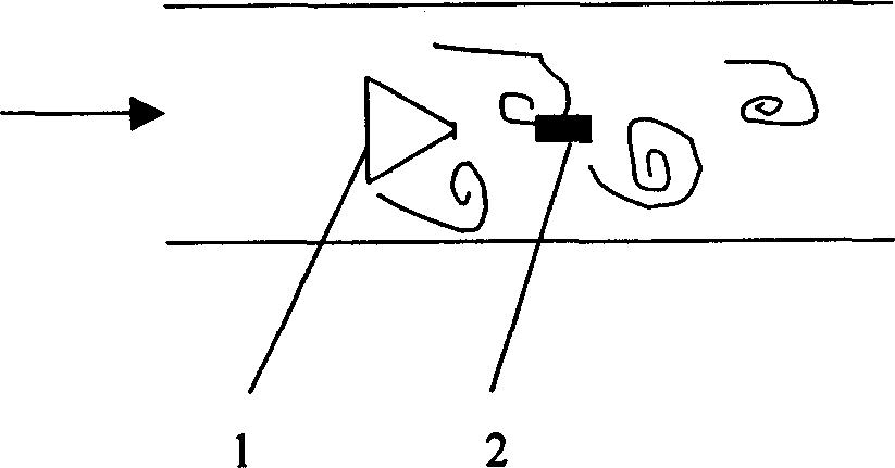
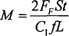
[0029] A pipe with an inner diameter of 50mm has a pressure of 1.208×10 5 For Pa saturated steam, the steam velocity is 28m / s. Place the truncated cone-shaped vortex generator 1 in the steam pipeline, with the facing side facing the direction of the incoming flow, and place the vortex detector behind the vortex generator, see figure 1 shown. The frequency f and amplitude F of the vortex signal are measured by the detector 1 F as follows:

[0030] f=481

[0031] f F =251N

[0032] The remaining parameter values ​​are as follows:

[0033] L=14×10 -3 m (Width of the upstream surface of the vortex street generating body)

[0034] St=0.24 (determined after the vortex generator is determined)

[0035] C 1 =0.9(empirical coefficient)

[0036] According to formula (3), the mass flow rate can be calculated as follows:

[0037] M = ρu = ...


PUM


Abstract

The invention relates to a detecting method for vortex street mass flux that belongs to liquid measuring technology field. The invention uses the vortex signal frequency caused by detecting vortex street generator and the force on the detector, the output signal on effect force is a periodic signal with certain amplitude. The mass flux would be calculated according to the detecting frequency and amplitude. The invention is easy to operate, high accuracy, broad application range and can be used for two phase fluxes detecting and high temperature environment detecting.

Description

technical field [0001] The invention belongs to the technical field of fluid measurement, and in particular relates to a detection method for vortex street mass flow. Background technique [0002] With the development of science and technology, human beings have gradually entered the information society, and the information industry has shown its strong vitality. The information industry has three pillars, detection technology, communication technology and computer technology, all of which are indispensable. Compared with communication and computer technology, detection technology is still in a backward state. From the point of view of information theory, detection technology is the main technology to obtain and transform various information, and is the basis for information transmission. It is conceivable that if the information obtained initially is unreliable, even if the subsequent processing technology is advanced, the results obtained will be meaningless. Therefore,...

Claims


Application Information

Patent Timeline
IPC IPC(8): G01F1/90
Inventor 李永光
Owner 上海卡诺节能环境工程有限公司
Learn More