Electrically driven camshaft adjuster

A technology of camshaft adjustment and wheel shaft, which is applied in the direction of valve devices, couplings, valve details, etc., can solve the problems of troublesome installation and pre-installation of servo motors, etc., and achieve the effect of reducing manufacturing costs

Inactive Publication Date: 2005-11-09
SCHAEFFLER TECH AG & CO KG
View PDF1 Cites 11 Cited by
  • Summary
  • Abstract
  • Description
  • Claims
  • Application Information

AI Technical Summary

Problems solved by technology

In addition, the installation of the device is very troublesome, because the integral servo motor cannot be pre-installed

Method used


Image

  • Electrically driven camshaft adjuster
  • Electrically driven camshaft adjuster
  • Electrically driven camshaft adjuster

Examples


Embodiment Construction

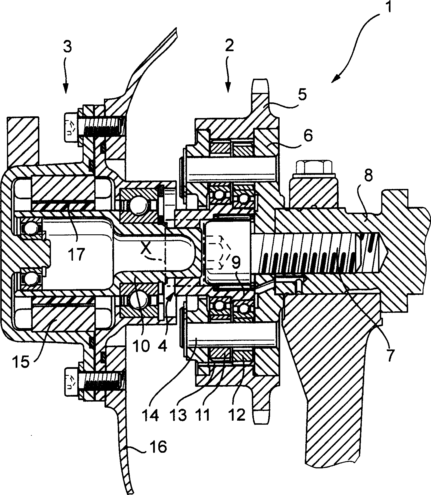
[0046] figure 1 An electric camshaft adjusting device 1 is shown with a gear mechanism 2 and an electric servomotor 3 , which are formed as separate units and are detachably connected via a coupling.

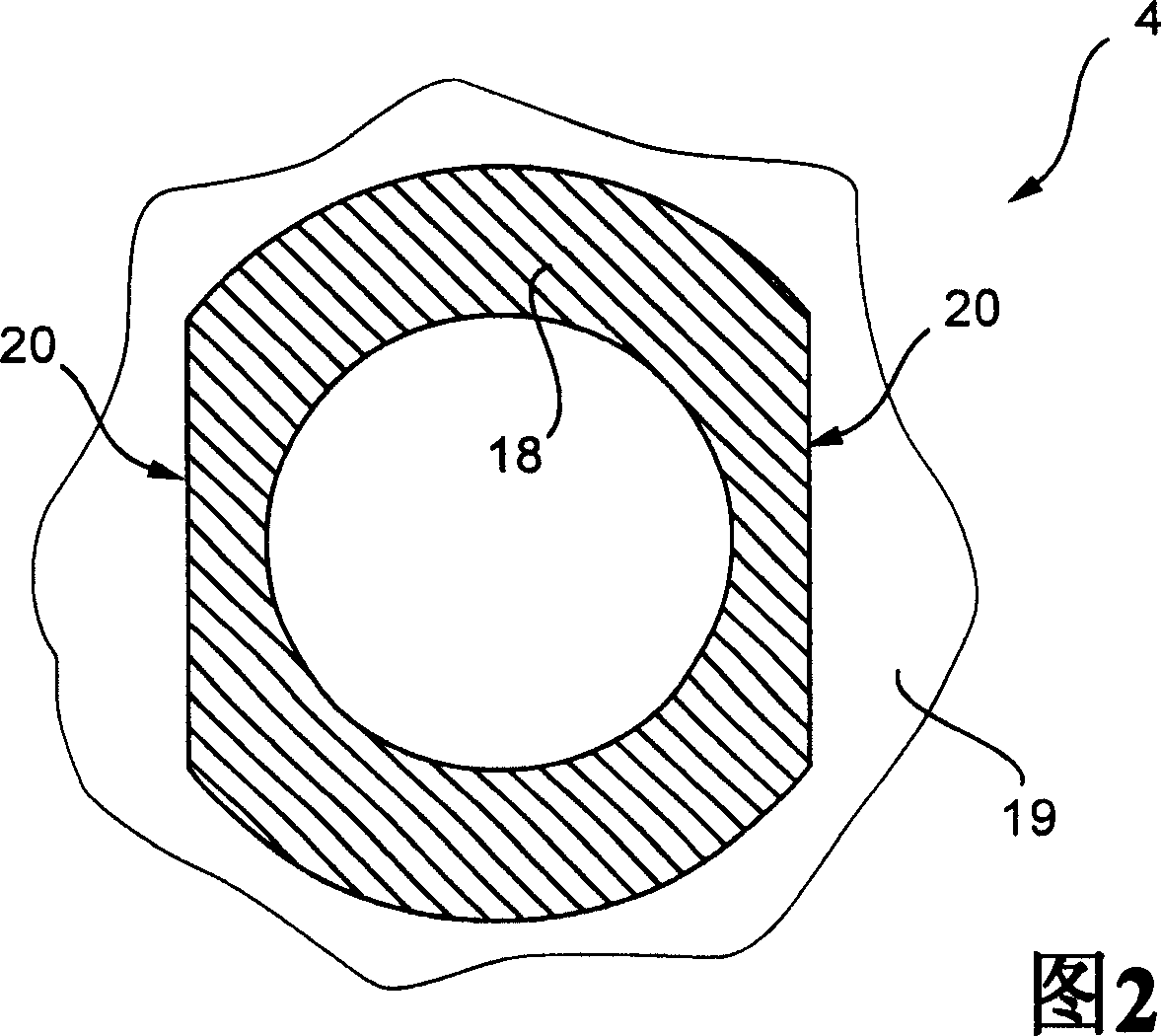
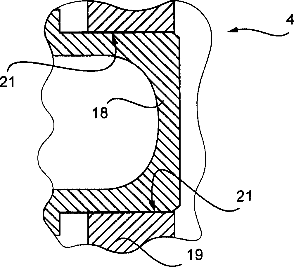
[0047] The speed change transmission mechanism 2 is a three-axis transmission mechanism, which has a high reduction ratio (reduction ratio range 1:30-1:250) and high efficiency as an eccentric transmission mechanism. The transmission 2 has a drive shaft and a driven shaft as well as an adjusting shaft 9 . The drive shaft is designed as sprocket 5 and is connected in a rotationally fixed manner to a crankshaft (not shown) via a chain (also not shown). The output shaft is formed as a closing wall 6 and is connected in a rotationally fixed manner to the camshaft 8 by means of a clamping screw 7 . The adjustment shaft 9 is formed as an eccentric shaft, and is connected to the servo motor shaft 10 through the double-edge shaft coupling 4 with practically no rotational play but can ...


PUM


Abstract

The invention relates to a camshaft adjuster (1) for adjusting and fixing the relative position of the angle of rotation of a camshaft (8) in relation to the crankshaft of a reciprocating piston internal combustion engine. Said adjusting device comprises a high transmission and friction-reduced adjusting gear mechanism (2), comprising a drive shaft which is rotationally fixed to the crankshaft, a driven shaft which is rotationally fixed to a camshaft (8) and an adjusting shaft (9) which is connected to an adjusting motor shaft (10) of an adjusting motor. A camshaft adjuster (1), which is economical to run, can be produced such that the adjusting gear mechanism (2) and the adjusting motor (3) are embodied as separate units and are connected together by a rotational backlash-free, disengaging clutch (4).

Description

technical field [0001] The invention relates to a camshaft adjusting device, in particular according to the preamble of claim 1, for adjusting and positioning the rotational angular position of a camshaft relative to a crankshaft of a reciprocating piston internal combustion engine. Background technique [0002] DE 41 10 195 A1 discloses a camshaft adjusting device for adjusting and positioning the relative rotational angular position of the camshaft relative to the crankshaft of a reciprocating piston internal combustion engine, with a high transmission ratio and low friction transmission mechanism, which There is a transmission shaft fixedly connected to the crankshaft, a driven shaft connected in a rotationally fixed manner to the camshaft, and an adjusting shaft connected to the servomotor shaft of the servomotor. [0003] In this solution, the servomotor shaft is integrally formed with the adjusting shaft of the transmission. As a result, the entire camshaft adjustment...

Claims


Application Information

Patent Timeline
Patent Type & Authority Applications(China)
IPC IPC(8): F01L1/352F16D3/76F16D3/77
CPCF01L1/022F16D3/76F01L2101/00F16D3/77F01L2201/00F01L1/352F01L2301/00F01L1/344F16D1/02F16D1/10
Inventor 延斯·舍费尔马丁·施泰格瓦尔德约格·德格尔曼约恩·海伍德
Owner SCHAEFFLER TECH AG & CO KG
Why Eureka
Try Eureka