Real time automatic non-invasion iris optical imaging device

An optical imaging, automatic technology, applied in medical science, human identification, equipment for testing eyes, etc., can solve problems such as center position deviation, motion blur, specular reflection interference, etc., to achieve high reliability, low complexity, and cost. low cost effect

Active Publication Date: 2005-12-07
SUZHOU SIYUAN KEAN INFORMATION TECH
View PDF1 Cites 25 Cited by
  • Summary
  • Abstract
  • Description
  • Claims
  • Application Information

AI Technical Summary

Problems solved by technology

At the same time, it provides real-time analysis and processing mechanism support for quality control of iris imaging images to solve motion blur, natural and fast use position posi...

Method used


Image

  • Real time automatic non-invasion iris optical imaging device
  • Real time automatic non-invasion iris optical imaging device
  • Real time automatic non-invasion iris optical imaging device

Examples


Embodiment 1

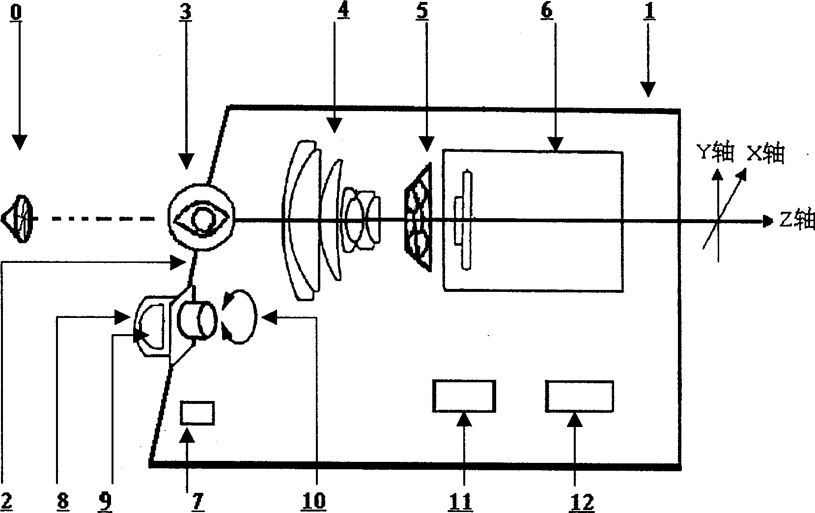
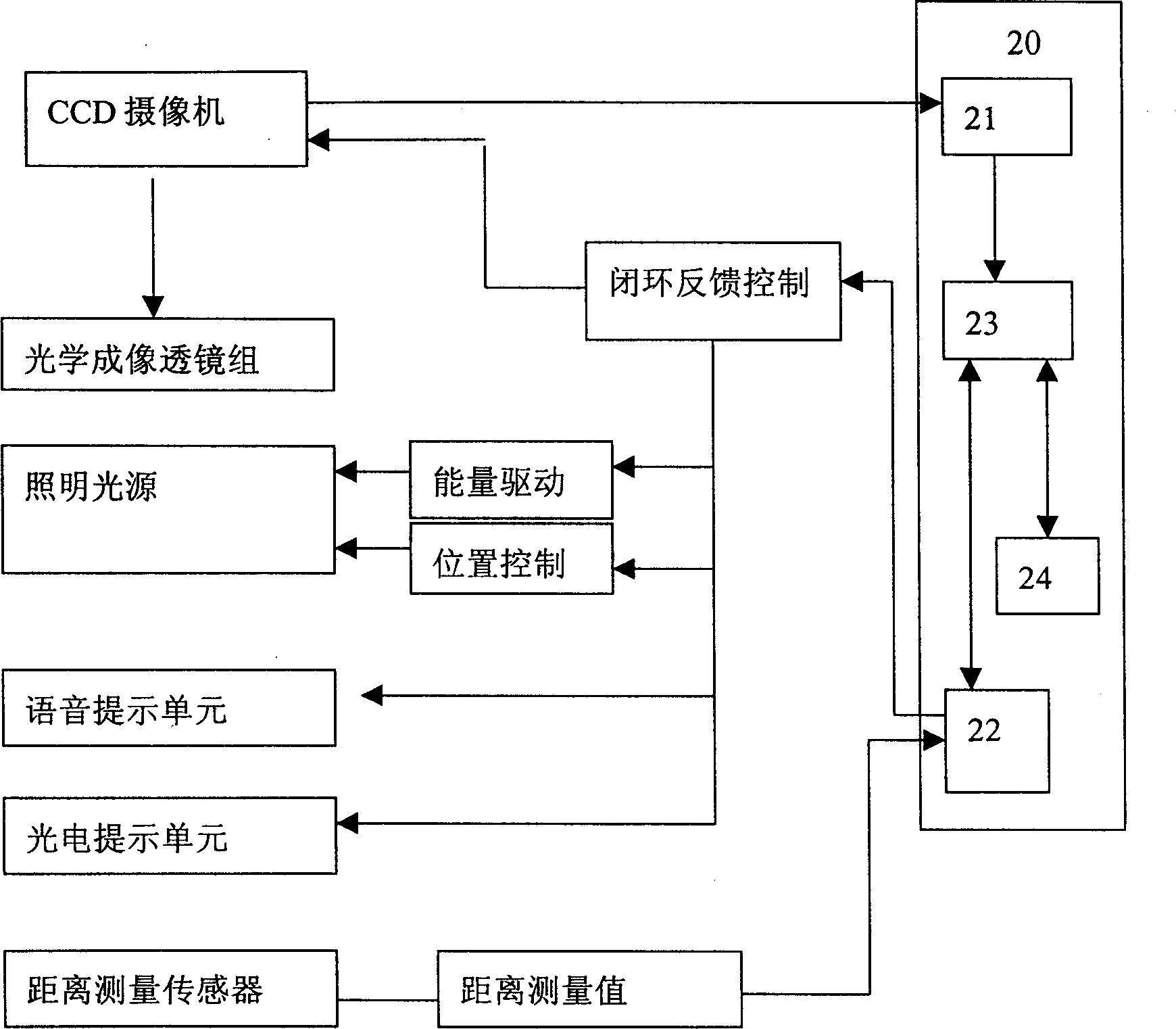
[0046] Embodiment 1, the components of the iris optical imaging device for iris collection can be obtained from figure 1 As can be seen in the figure, it includes a closed casing 2, and the near-infrared band optical reflection filter 3, the optical imaging lens group 4 with variable focus and focusing function, the CCD video camera 6, and the PSD distance are arranged in sequence on the optical axis in the casing. Measuring sensor 7 and lighting source system, said lighting source system consists of near-infrared band lighting source 9, near-infrared band diffusion / scattering filter 8, an energy driver capable of changing the radiation intensity of the light source, and a controller for adjusting the position of the lighting source 10, and is provided with an image processing control unit 20, a voice prompt unit 11 and / or a photoelectric prompt unit 12 for stable and reliable real-time closed-loop feedback control of the optical imaging device. The image processing control un...

Embodiment 2

[0224] Embodiment 2. Compared with Embodiment 1, the optical imaging device of this embodiment is smaller in size, lower in power consumption, very low in cost, has fewer components, relatively simpler control process, and more reliable optical imaging device. In this way it is very suitable as a personal special device, such as a portable iris optical imaging device designed with a USB digital interface, which is greatly convenient to use. Combining with Embodiment 1, the composition and working principle of the optical imaging device in Embodiment 2 will be described.

[0225] It consists of a closed casing, and the optical axis in the casing is arranged with near-infrared band optical reflection filters, fixed focal length optical imaging lens groups, CCD video cameras, and lighting source systems. The lighting source system consists of near-infrared band Lighting source, near-infrared band diffusion / scattering filter for airtight lighting source, controller for adjusting t...


PUM


Abstract

The invention relates to a real-time automatic non-injury iris optical imaging device which provides an optical imaging device with iris biological test purpose. It can real-time images iris grain image. It comprises a sealed casing. Near infrared band optical filter, optical imaging lens array, video camera and light source for lighting system are grading arranged on the optical axis of the casing; the invention also has image handling control unit which can do real-time closed-loop feedback control to the optical imaging device.

Description

【Technical field】 [0001] The invention relates to an optical imaging device for iris biometrics, capable of real-time imaging of high-quality iris texture images, in particular a device capable of obtaining high-quality iris texture optical imaging in a real-time, automatic and non-invasive manner, belonging to Opto-mechanical integration, automatic control technology field. 【Background technique】 [0002] Bum Chul Kim et al "Iris Recognition System" U.S. Patent No.: US6,594,377B1 ("IRIS RECOGNITION SYSTEM" US PATENT NUMBER: US6,594,377 B1 Jul, 15, 2003) proposed a non-invasive method that does not strictly limit the use distance device. It consists of a concave container that can be rotated up and down. In the container, there are ultraviolet cut-off mirrors, flat cold light mirrors, imaging lenses, cameras, several near-infrared band lighting sources, distance measurement sensors, and control units. But 1) the device is too bulky; 2) the flat cold light mirror is not con...

Claims


Application Information

Patent Timeline
IPC IPC(8): A61B3/14A61B5/1171
Inventor 倪蔚民
Owner SUZHOU SIYUAN KEAN INFORMATION TECH
Why Eureka
Try Eureka