Supercharge Your Innovation With Domain-Expert AI Agents!

Radiation system, lithographic apparatus, device manufacturing method and device manufactured thereby

A technology of radiation system and projection device, which is applied in the field of radiation system and can solve problems such as short wavelength, radiation loss, and inappropriateness

Inactive Publication Date: 2005-12-14
ASML NETHERLANDS BV
View PDF1 Cites 6 Cited by
  • Summary
  • Abstract
  • Description
  • Claims
  • Application Information

AI Technical Summary

Problems solved by technology

The use of partially reflective mirrors in the direction of the rest of the lighting system will result in a loss of radiation (i.e. energy)
In addition, the above-mentioned partially reflective mirrors are not suitable for the extremely short wavelengths combined with the high radiation intensity used in BUV lithography systems

Method used


Image

  • Radiation system, lithographic apparatus, device manufacturing method and device manufactured thereby
  • Radiation system, lithographic apparatus, device manufacturing method and device manufactured thereby
  • Radiation system, lithographic apparatus, device manufacturing method and device manufactured thereby

Examples


Embodiment Construction

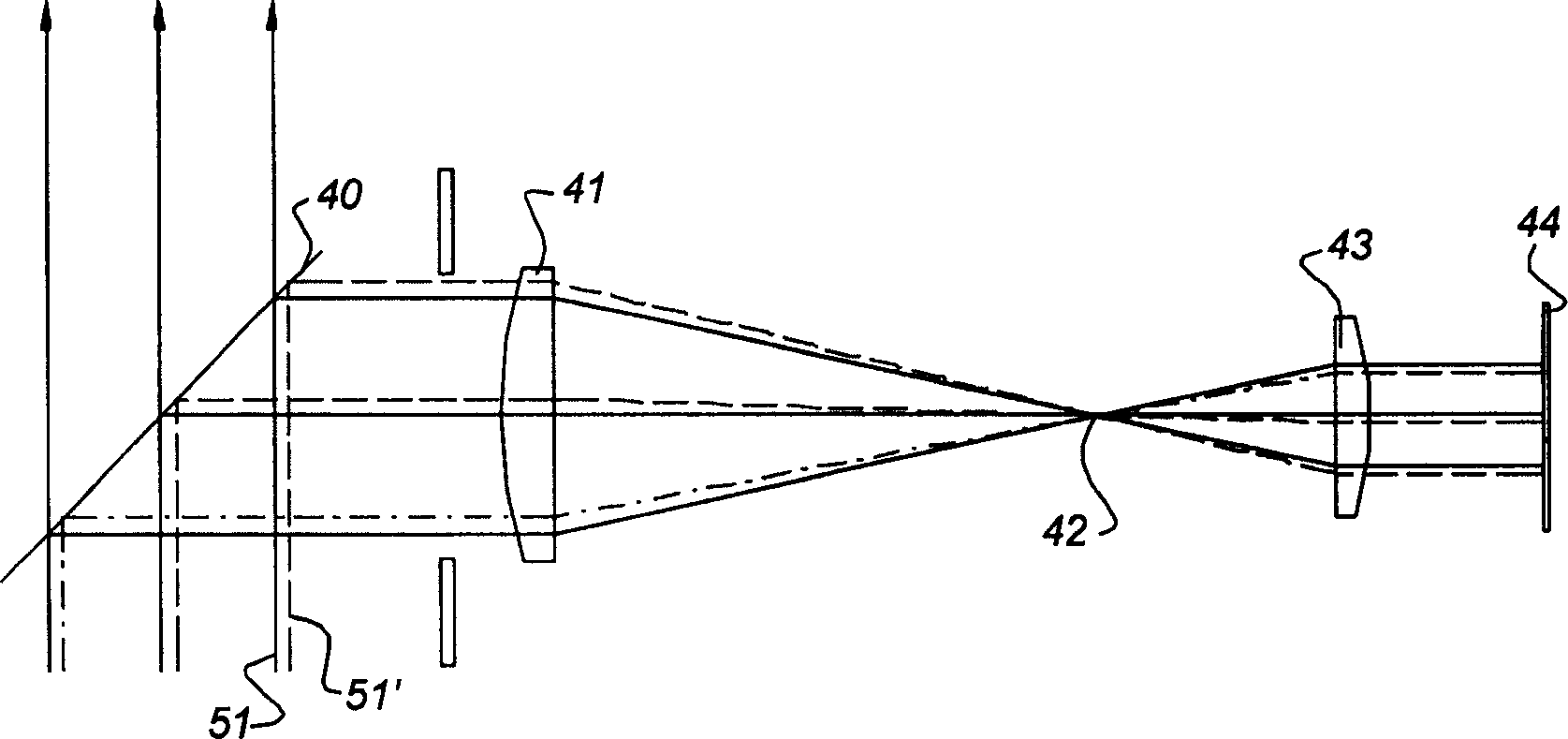
[0036] refer to figure 1 , the beam measurement system is fixed to the illumination system (not shown) according to the prior art, and the beam measurement system includes a partially transmissive / partially reflective mirror 40 positioned between the radiation beam 51 emitted from the radiation generator (not shown). middle. figure 1 The three arrows in represent the radiation passing through the mirror 40 . Part of the radiation beam 51 is reflected onto the lens 41 . Lens 41 is arranged to form intermediate focus 42 , lens 43 is arranged to receive radiation from intermediate focus 42 , lens 43 is arranged to form a reduced image of beam 51 on position sensor 44 . The position sensor 44 is arranged to detect the position of the beam 51 on the position sensor 44 . When the radiation generator is incorrectly positioned relative to the illuminator (i.e. the measurement system), the radiation beam 51' will hit the mirror 40, the radiation from the beam 51' being indicated by ...


PUM


Abstract

A radiation system comprising a radiation generator for generating a radiation beam, a source, and an illumination system for receiving the radiation beam and providing a radiation projection beam. The illumination system includes a beam measurement system for measuring at least one of a position and an inclination of the radiation beam relative to the illumination system, and a projection device for redirecting a partial section of the radiation beam to the beam measurement system. A beam measurement system may include a plurality of position sensors, the output of which may be used to determine inaccurate alignment of the radiation source relative to the illumination system. The diaphragm is connected to the collector of the radiation generator so that in addition to X, Y and Z corrections, Rx, Ry and Rz corrections are also possible.

Description

technical field [0001] The invention relates to a radiation system, a lithographic apparatus comprising the radiation system, and a method for manufacturing a device. Background technique [0002] A lithographic apparatus is a machine that provides a desired pattern onto a substrate target. Lithographic apparatus can be used, for example, in the fabrication of integrated circuits (ICs). In such an environment, a patterning device, such as a mask, can be used to create a circuit pattern corresponding to the individual layers of the IC, and this pattern can be imaged onto a target portion of the substrate (e.g., a silicon wafer) (e.g. , comprising a portion of one or more dies), the substrate has a layer of radiation-sensitive material (resistor). Typically, a single substrate will contain a network of adjacent target portions that are sequentially exposed. A known lithographic apparatus comprises a stepper in which each target portion is irradiated by exposing the entire p...

Claims


Application Information

Patent Timeline
Patent Type & Authority Applications(China)
IPC IPC(8): G01B11/00G01B11/26G02B5/08G03F7/20H01L21/027
CPCG03F7/70141G03F7/70641G03F7/70858G03F7/70008G03F7/706847G03F7/706851G03F7/7085G03F7/702G03F7/70075
Inventor M·M·T·M·迪里奇斯M·F·A·厄林斯H·-J·沃尔马O·W·V·弗里恩斯
Owner ASML NETHERLANDS BV
Features
  • R&D
  • Intellectual Property
  • Life Sciences
  • Materials
  • Tech Scout
  • Unparalleled Data Quality
  • Higher Quality Content
  • 60% Fewer Hallucinations
Learn More