Supercharge Your Innovation With Domain-Expert AI Agents!

Application of laser emitter on CD driver

A technology of laser emission and optical drive, applied in the direction of beam source, optical recording head, etc., can solve the problems that the cost of components cannot be effectively reduced, the assembly of optical read-write head 1 is complicated, etc.

Inactive Publication Date: 2005-12-14
LITE ON IT
View PDF0 Cites 0 Cited by
  • Summary
  • Abstract
  • Description
  • Claims
  • Application Information

AI Technical Summary

Problems solved by technology

As shown in Figure 1(b), it is a structural schematic diagram of installing the temperature sensing device 13 in the optical read-write head 1, but this structure will cause the assembly of the optical read-write head 1 to be relatively complicated, resulting in that the cost of the components cannot be effectively reduced, and how to To improve the deficiency of this existing means is to develop the main purpose of the present invention

Method used


Image

  • Application of laser emitter on CD driver
  • Application of laser emitter on CD driver
  • Application of laser emitter on CD driver

Examples


Embodiment Construction

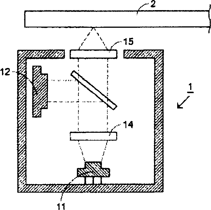
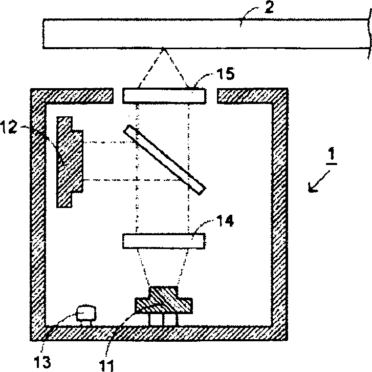
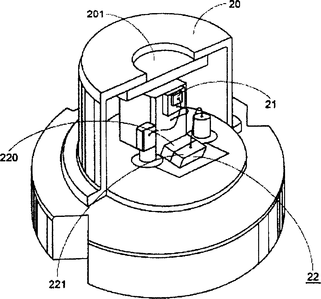
[0020] See figure 2 , which is a structural diagram of a preferred embodiment of a laser emitting device developed by the present invention to improve the defects caused by the separate arrangement of the existing semiconductor laser module 11 and the temperature sensing device 13. The laser emitting device is mainly used in an optical drive (this figure not shown in ) and an optical disc (not shown in this figure), this preferred embodiment mainly includes a casing 20, which is arranged in the optical pickup head of the optical drive or in the optical pickup head, the casing The body 20 also has a light-transmitting part 201, and the laser emitted by the laser emitting component 21 that can be completed by a laser diode is transmitted through the light-transmitting part 201, and the feature of this embodiment is that the light detecting component 220 and the temperature sensing component 221 is mainly completed simultaneously on a silicon substrate 22 by a CMOS process. The ...


PUM


Abstract

The laser emitting device applied between CD drive and CD includes one casing set inside the CD drive and with one transparent part; one laser emitting assembly inside the casing and connected electrically to the CD drive to emit one laser beam penetrating the transparent part; and one semiconductor substrate inside the casing and connected electrically to the CD drive. On the semiconductor substrate, there are one light detecting assembly and one temperature sensing assembly, the light detecting assembly receives the laser the laser emitting assembly emits and monitors its strength through converting it into one electric signal for the CD drive to use, and the temperature sensing assembly responds the temperature change inside the casing to generate one temperature change signal for the CD drive to refer on.

Description

technical field [0001] The invention relates to a laser emitting device applied to an optical drive, especially a laser emitting device applied to an optical drive. Background technique [0002] Please refer to Fig. 1(a), which is a schematic diagram of the structure of the optical read-write head 1 in the optical disc burner. The slice 2 is reflected back to the optical head 1 to be received by the photodetector 12 . When the optical disc burner writes to the optical disc 2, the semiconductor laser module 11 emits a laser with a specific power range to engrave a mark on the recording material of the optical disc 2, that is, the laser power for recording is a If the limited range is too high or too low, it will easily lead to poor writing quality or even writing failure. [0003] The optical discs 2 of different materials also need to adjust the laser power, and the single-burn optical discs or rewritable optical discs also need different laser powers, and ordinary optical...

Claims


Application Information

Patent Timeline
IPC IPC(8): G11B7/127
Inventor 曹志强廖正尧
Owner LITE ON IT
Features
  • R&D
  • Intellectual Property
  • Life Sciences
  • Materials
  • Tech Scout
  • Unparalleled Data Quality
  • Higher Quality Content
  • 60% Fewer Hallucinations
Learn More