Liquid crystal display device
A liquid crystal display device and liquid crystal display technology, which are applied to identification devices, lighting devices, cooling/heating devices of lighting devices, etc., can solve the problems of low luminous efficiency and lifespan of LED light sources, increased heat generation, and shortened lifespan. , to achieve the effect of inhibiting the reduction of luminous efficiency, reducing the temperature rise, and preventing damage to the LED light source
- Summary
- Abstract
- Description
- Claims
- Application Information
AI Technical Summary
Problems solved by technology
Method used
Image

Examples
Embodiment 1
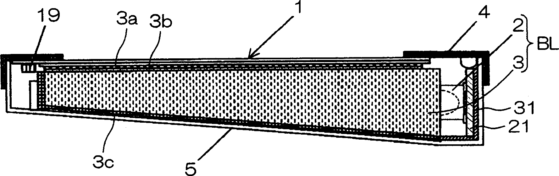
[0246] With regard to the thermally conductive elastic sheet 31, an elastic sheet (the model produced by Japan Sumitomo Slim (Co., Ltd.) is No.5509) with a cross-section having heat dissipation properties that can be used is No.5509. As for the heat dissipation substrate 5, a thickness of 2 mm of aluminum, the mounting substrate 21, the thermally conductive elastic sheet 31, and the heat dissipation substrate 5 are fixed in surface contact.
[0247] The thermal conductivity of various materials used here is 0.45W / m·k for the mounting substrate 21 composed of glass epoxy resin, 5W / m·k for the thermally conductive elastic sheet 31, and 236W / m·k for the aluminum used as the heat dissipation substrate 5. k.
[0248] In addition, magnesium or iron may be used as the heat dissipation substrate 5 . In addition, the thermal conductivity of magnesium is 157W / m·k, and the thermal conductivity of iron is 83.5W / m·k. If the heat dissipation is poor, it is also possible to increase the thi...
Embodiment 2
[0256] Between the mounting substrate 21 and the thermally conductive elastic sheet 31 , and between the thermally conductive elastic sheet 31 and the heat dissipation substrate 5 , the fluid 17 (thermally conductive compound) was applied, and the same temperature measurement as in Example 1 was performed.
[0257] As for the heat conduction compound, SC102 produced by Japan Toray Dou Corning Silicone Co., Ltd. can be used, and the mounting substrate 21 and the thermally conductive elastic sheet 31 and the heat dissipation substrate 5 are fixed in surface contact. The thermal conductivity of the thermally conductive compound is 0.8 W / mk.
[0258] Heat conduction compound is a clay-like state in which fine ceramic particles with high thermal conductivity, etc., are mixed with a high-viscosity oil component. , so that the thermal conductivity becomes better.
[0259] Using a liquid crystal display 1 with a display area size of 4.7 inches, 16 LED light sources 2 are arranged and...
Embodiment 3
[0264] In addition to the configuration of Example 1, a heat-conductive elastic member 20 was added, and the same temperature measurement as in Example 1 was performed.
[0265] The thermally conductive elastic member 20 can use a plate-shaped elastic sheet (model No.5509 produced by Japan Sumitomo Slim (Co., Ltd.)) with heat dissipation characteristics, so that the light incident side end surface of the mounting substrate 21 and the light guide plate 3 is a surface. fixed by contact.
[0266] The light emitted by the LED light source 2 and the heat generated at the same time also pass through the mounting substrate 21 and the thermally conductive elastic member 20 , and are released to the light guide plate 3 . Therefore, the heat transferred from the mounting substrate 21 to the heat dissipation substrate 5 is dissipated from the three lines of the mounting surface, the back surface, and the lower end surface of the mounting substrate 21 .
[0267] Using a liquid crystal di...
PUM
| Property | Measurement | Unit |
|---|---|---|
| Thermal conductivity | aaaaa | aaaaa |
| Thermal conductivity | aaaaa | aaaaa |
| Thermal conductivity | aaaaa | aaaaa |
Abstract
Description
Claims
Application Information
 - Generate Ideas
- Intellectual Property
- Life Sciences
- Materials
- Tech Scout
- Unparalleled Data Quality
- Higher Quality Content
- 60% Fewer Hallucinations
Browse by: Latest US Patents, China's latest patents, Technical Efficacy Thesaurus, Application Domain, Technology Topic, Popular Technical Reports.
© 2025 PatSnap. All rights reserved.Legal|Privacy policy|Modern Slavery Act Transparency Statement|Sitemap|About US| Contact US: help@patsnap.com