Precision vibration damping and locating device

A positioning device and precise technology, applied in non-rotational vibration suppression, electrical components, semiconductor/solid-state device manufacturing, etc., to achieve precise position positioning, high repeat positioning accuracy, and small device deformation.

Inactive Publication Date: 2006-01-25
SHANGHAI MICRO ELECTRONICS EQUIP (GRP) CO LTD
0 Cites 41 Cited by

AI-Extracted Technical Summary

Problems solved by technology

[0005] The purpose of the present invention is to provide a precision vibration reduction and positioning device, which solves the technical defects of using a s...

Method used

As shown in Figure 1: whole vibration damping device comprises passive vibration damping component and active vibration damping executive component to form jointly, and wherein passive vibration damping component is mainly a kind of cavity structure, and horizontal and vertical all can have certain range of motion, The cavity 8 can be filled 7 with gas, rubber, metal rubber or liquid. If the filling medium is liquid or gas, the cavity 8 needs to be sealed, and the low-frequency resonance frequency of the system is controlled by the solenoid valve 14 to realize active control. Connected to the vibration damping platform 13 through the piston mechanism supported by these filling carriers, the vibration source is firstly isolated or attenuated to a greater extent in a wider frequency band; there is an active vibration damping component and a passive vibration damping component The control components are connected, consisting of vibration sensors (absolute speed sensor 2, horizontal position sensor 9, vertical position sensor 10), signal processor, data collector, arithmetic decision maker, motor driver, and two horizontal and vertical Linear motors (vertical linear motor 3 and horizontal linear motor 4) are used for precise positioning, so that the object to be damped is isolated from external interference, or the system maintains high-precision position positioning after the interference is quickly attenuated.
[0030] The cavity 8 can be sealed and filled with gas or liquid; it can also be non-sealed and filled with damping materials such as rubber, sponge, or metal rubber. The advantage of this de...

Abstract

The invention relates to an effectively damping multi-freedom locating device with the passive control as the principal and the active control as the auxiliary, used to realize accurate horizontal and height location, and comprising passive damping component and active damping component, where the passive damping component is of a cavity structure able to have a certain horizontal and vertical moving range and is connected through the cavity-supported piston mechanism to a damped platform for isolating or attenuating the vibrating source in a wider frequency band by a large margin; an active control component joins the damped vibrating components, and is composed of vibration sensor, signal processor, data collector, operation policy maker, electric machine driver, and two linear electric machines in the vertical and horizontal directions, so as to make accuracy location. The invention has compact structure, high reliability, high repeated locating accuracy, strong adaptability, small device deformation, moving stability and meets the strict requirements of the precision devices, such as photo-etcher, etc. at normal temperature.

Application Domain

Technology Topic

Policy makerRoom temperature +12

Image

  • Precision vibration damping and locating device
  • Precision vibration damping and locating device
  • Precision vibration damping and locating device

Examples

  • Experimental program(1)

Example Embodiment

[0027] A preferred embodiment is given below in conjunction with the drawings to further describe the present invention.
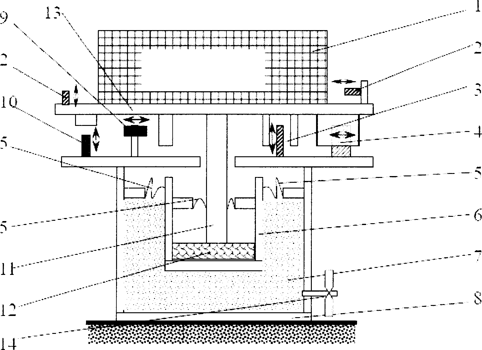
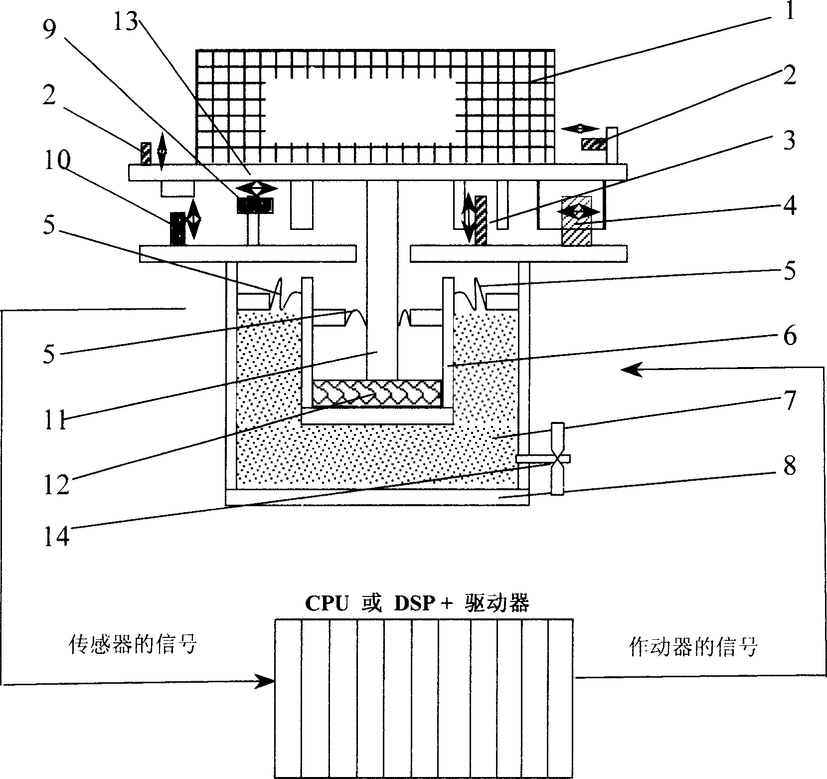
[0028] Such as figure 1 Shown: the entire damping device includes passive damping components and active damping executive components. The passive damping component is mainly a cavity structure, which can have a certain range of movement in both horizontal and vertical directions. The cavity 8 can be made of gas, Rubber, metal rubber or liquid filling 7. If the filled medium is liquid or gas, the cavity 8 needs to be sealed, and the solenoid valve 14 is used to realize active control to control the low-frequency resonance frequency of the system. The piston mechanism supported by these filling carriers is connected to the vibration damping platform 13, and the vibration source is first isolated or attenuated in a relatively wide frequency band; there is an active part between the damped component and the passive damping component. The control components are connected by the vibration sensor (absolute speed sensor 2, horizontal position sensor 9, vertical position sensor 10), signal processor, data collector, arithmetic decision maker, motor driver, and two horizontal and vertical directions Linear motors (vertical linear motors 3 and horizontal linear motors 4) are composed to perform precise positioning to isolate the damped object from external interference, or after the interference is quickly attenuated, the system can still maintain high-precision position positioning.
[0029] Among them, the cavity 8 has a movable piston 6, which is connected by a sealing film or an elastic disc spring 5, such as figure 2 As shown, the cross-section of the sealing film 5 can be in various shapes, semicircular (2a), triangle or V-shaped (2b), foldable or M (2c), s-type (2d), MV and other combinations ( 2e) and a variety of corrugated forms (2f) and other structures that can produce flexible deformation.
[0030] The cavity 8 can be sealed and filled with gas or liquid; it can also be non-sealed and filled with vibration damping materials such as rubber, sponge, or metal rubber. The advantage of this device is that it can generate a high reaction force to support the heavier working platform 13, but when it is filled with gas or liquid, the disadvantage is that a cavity seal design is required, but the solenoid valve 14 can be used for active control. To compensate for the narrow bandwidth of the liquid/aerodynamic force, the fast and slow characteristics can be selected and adjusted, so that the system can be reset quickly after the interference is attenuated. In order to maintain accurate positioning of the vibration-isolated object, it is necessary to use the horizontal position sensor 9 and the vertical position sensor 10 (such as a non-contact eddy current sensor) for position measurement and feedback, and drive the linear motors 3 and 4. Since the passive system is generally a mass spring system, it generates more damping through gas/liquid. There is a speed sensor 2 in the horizontal and vertical directions. After the speed sensor 2 is used to measure the absolute speed, the speed signal is used to drive the horizontal linear motor 4 and the vertical linear motor 3 to generate a main power for active control. Although a linear motor converts electrical energy into mechanical energy, it still has a very high bandwidth. The main passive system of this device is connected and working in parallel or in parallel. The damping system is firstly isolated by the slower force generated by the passive system, and then according to the position signal, the gas/hydraulic power control loop and the fast response The loop formed by the linear motor generates force for control.
[0031] The piston 6 is supported by the filler 7 and has a connecting rod 11 connected to the vibration damping platform 13 to form a counter-support force for the object 1 to be damped/isolated for passive vibration isolation. A sealing film or elastic disc spring 5 is connected between the piston 6 and the connecting rod 11, and the section of the sealing film is semicircular, or triangular, or V-shaped, or folded, or M-shaped, or S-shaped, or MV Combination shape, or corrugated shape. When liquid or gas is used for filling, the active valve 14 can be used to adjust the buffer force to achieve optimal control. In the horizontal direction, the piston connecting rod is flexibly supported by the damping material 12 to form a small pendulum movement, forming a buffer force for horizontal vibration isolation. The damping force is formed by the feedback of the horizontal and vertical speed sensors 2; the position signals obtained by the horizontal position sensor 9 and the vertical position sensor 10 are fed back by the vertical linear motor 3 and the horizontal linear motor 4, Obtain rapid response force and perform precise position compensation.
[0032] The electrical components of the system include: pneumatic/hydraulic power controllers and control valves, linear motors, sensors (such as position sensors, speed sensors, temperature sensors), preamplifiers, connecting cables and connectors, driver amplifiers, servo boards, etc.
[0033] The feedback control loop of the electromechanical system includes two parts, one is the gas/hydraulic power control loop; the other is the electrical control loop, such as Figure 4 Shown. The first loop is mainly to drive the gas-liquid/power loop to achieve vertical movement. It contains three main feedback loops, namely the position feedback loop, the pressure feedback loop, and the pseudo-pressure loop obtained through velocity differentiation, with additional external signal injection The realization of jitter control is mainly for the crawling state of the actuator, such as Figure 5 Shown. In the second electrical feedback loop, the actuator is a linear motor, which not only controls the vertical direction, but also controls the horizontal direction. In this loop, the vertical and horizontal position feedback loops are included. , Inertial damping feedback loop, noise filtering loop and jitter compensation, as well as feedforward compensation of moving parts in motion, such as Figure 7 Shown.
[0034] In summary, the above descriptions are only preferred embodiments of the present invention, and are not used to limit the scope of implementation of the present invention. That is, all equivalent changes and modifications made in accordance with the content of the patent application scope of the present invention should be within the technical scope of the present invention.

PUM

no PUM

Description & Claims & Application Information

We can also present the details of the Description, Claims and Application information to help users get a comprehensive understanding of the technical details of the patent, such as background art, summary of invention, brief description of drawings, description of embodiments, and other original content. On the other hand, users can also determine the specific scope of protection of the technology through the list of claims; as well as understand the changes in the life cycle of the technology with the presentation of the patent timeline. Login to view more.

Similar technology patents

Positioning mechanism

InactiveCN104723002AOvercoming difficult positioningAccurate positioningWelding/cutting auxillary devicesAuxillary welding devicesSoftware engineeringWelding process
Owner:ANHUI JIANGHUAI AUTOMOBILE GRP CORP LTD

Novel hinge structure device

InactiveCN109277726AThe workpiece is stable and firmAccurate positioningWelding/cutting auxillary devicesAuxillary welding devicesRocker armMagnet
Owner:SHANGHAI JUNJI MACHINE EQUIP MFG CO LTD

Classification and recommendation of technical efficacy words

  • Accurate positioning
  • Compact structure

High-precision camera pan/tilt head

Owner:TIANJIN BOTAITIANYU TECH DEV CO LTD

Partial discharge collecting and positioning method, device and system

InactiveCN111175614AImprove sampling accuracyAccurate positioningPosition fixationTesting using acoustic measurementsComputational physicsPower equipment
Owner:HENAN PINGGAO ELECTRIC +2
Why Eureka
Try Eureka