Damper

A damper and damping technology, applied in the direction of shock absorber, shock absorber, brake type, etc., can solve the problems of increased manufacturing cost, inability to adjust the use, increased weight, etc., to achieve compact weight, cheap manufacturing, and easy The effect of installation

Inactive Publication Date: 2006-01-25
FUKOKU CO LTD
View PDF1 Cites 15 Cited by
  • Summary
  • Abstract
  • Description
  • Claims
  • Application Information

AI Technical Summary

Problems solved by technology

[0003] (1) Since the flow path needs to be formed in the box, the structure is complicated and the manufacturing cost is increased
[0004] (2) There are many fluids and internal components that constitute the flow path, and the weight increases
Therefore, since the crimping force between the inner wall surface of the box and the peripheral surface of the flange 23 is the largest at rest, the static friction is also relatively large. Especially when it is used as a cylindrical buffer (shock absorber), it is difficult to rotate in the direction of rotation. Therefore, the installation is not good
[0009] (2) Since the damping force is adjusted according to the ease of deformation of the flange 23, a space to allow deformation is required on the large deformation side
[0010] (3) Support plates made of stronger materials that can withstand deformation loads must be used
[0013] (1) Due to the need to form a flow path in t

Method used


Image

  • Damper
  • Damper
  • Damper

Examples


Embodiment Construction

[0061] Hereinafter, an example of the linear motion type damper device according to the first embodiment of the present invention will be described with reference to the drawings.

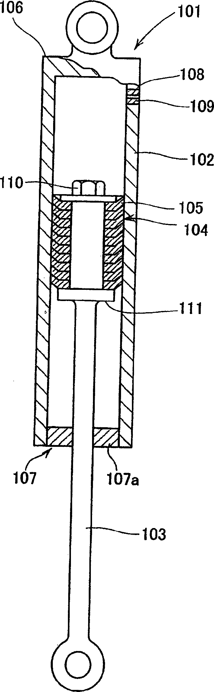
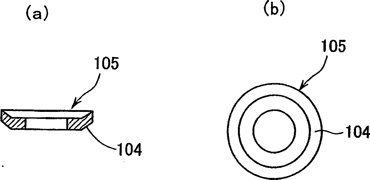
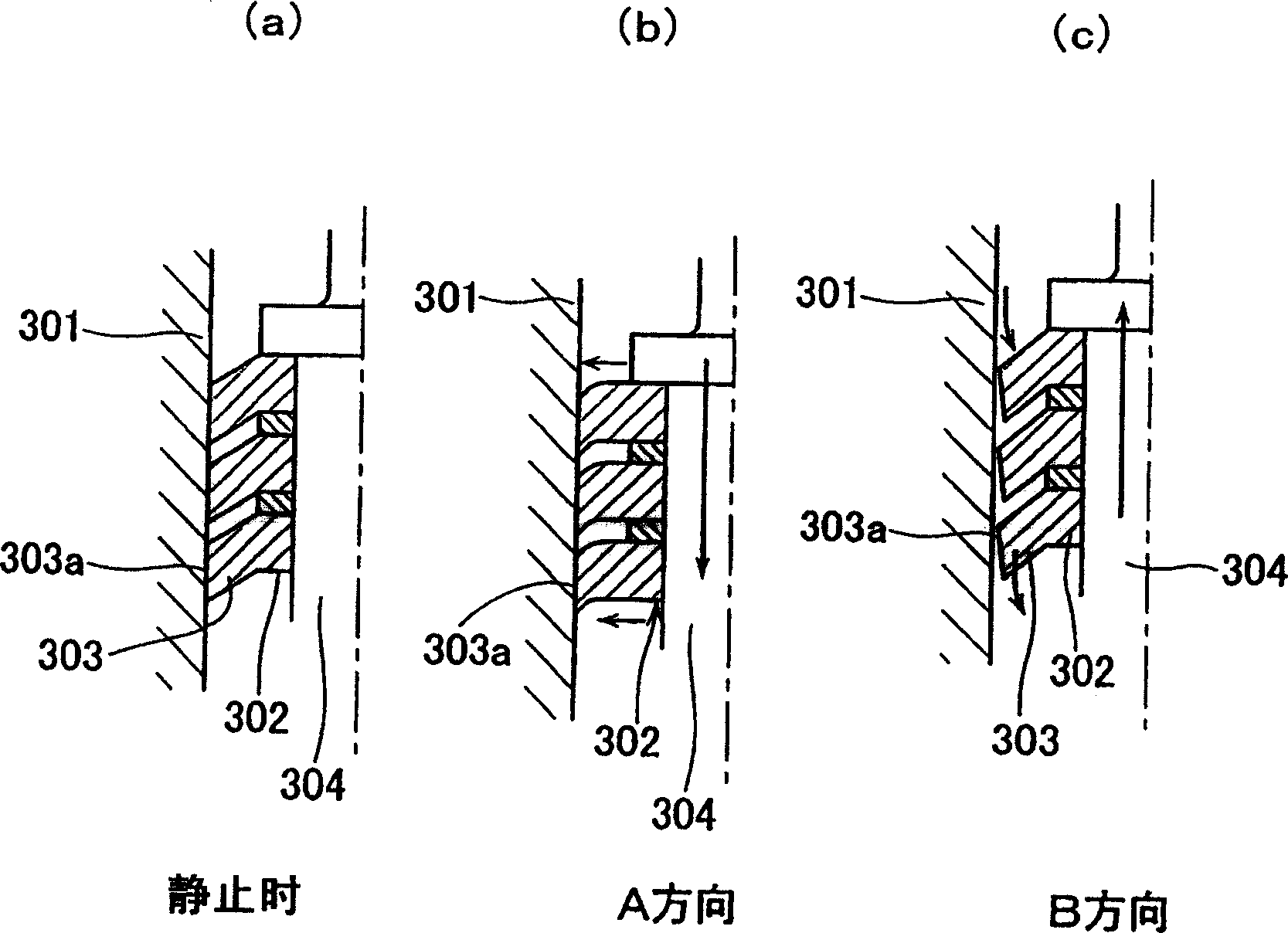
[0062] figure 1 is a schematic cross-sectional view of the linear motion damper device of the present invention, figure 2 Shown is a cross-sectional view of the flange member used in the damper unit, and image 3 Shown in is a state diagram for illustrating the operation of the damper device.

[0063] Such as figure 1 As shown, the damper device includes a cylindrical box 102 in a linear motion damper device 101, a piston rod 103 reciprocating in the box, and a flange member 104 as a disc-shaped braking member. . The flange member has an outer diameter slightly larger than the inner diameter of the assembled box in a free state. Moreover, tapers are added in one direction toward the peripheral edge on the two sides corresponding to the part away from the center of the flange member. The peri...


PUM


Abstract

A damping device for use in industrial machinery and tools comprising a housing ( 102, 602 ) and a flange member ( 104, 604 ) arranged in the housing, wherein at least portions of the flange member apart from the center thereof are composed of an elastic material and inclined with respect to the axial direction or the radial direction of the rotational axis and the flange member is so designed that the peripheral face thereof is brought into contact with the inner wall of the housing. This device can generate a damping force which may be drastically changed depending on the operating directions and thus permits stable damping. In the direct acting type one, the flange member ( 104 ) is tapered on the corresponding both faces towards the periphery thereof, it never requires the formation of any space for allowing any deformation on the largely deformed side, the device can thus be miniaturized in the axial direction and permits the reduction of the weight thereof and it can operate even in response to motions having a fine amplitude to thus show excellent damping characteristics. In the rotary type one, the flange member ( 604 ) comprises an engaging member capable of being engaged with a shaft body ( 603 ) and is provided with projected or convex portions ( 604 a) on its outer periphery. The projected portions are inclined towards the radial direction of the rotating shaft to thus efficiently show their excellent differential rotation-damping characteristics and the damping characteristics may arbitrarily be controlled. These damping devices can be used as dampers for suspensions of bicycles, rotary dampers applied to chairs and dampers for opening and closing doors.

Description

technical field [0001] The present invention relates to a damper device, in particular to a damper device used in industrial machines, which generates a damping force during the differential motion between two members, and can generate a damping force that is significantly different due to the direction of motion device. Especially suitable for damper devices that can damp linear reciprocating differentials and rotary differentials. Background technique [0002] As a damper device, there has been known a so-called linear motion type oil damper device that uses flow resistance such as oil, such as a shock absorber used in automobiles. This oil damper device has the following problems. [0003] (1) Since a flow path needs to be formed in the box, the structure is complicated and the manufacturing cost increases. [0004] (2) There are many fluids and internal components constituting the flow path, resulting in increased weight. [0005] For this reason, as a damper device ...

Claims


Application Information

Patent Timeline
IPC IPC(8): F16F9/00F16F9/32F16F7/08F16F7/04F16D63/00
Inventor 千叶雅章
Owner FUKOKU CO LTD
Why Eureka
Try Eureka