Vortex compressor

A scroll compressor and scroll technology, applied in the field of scroll compressors, can solve the problems of increased power loss, reduced discharge resistance, narrowing of the central chamber T3, etc., to achieve increased communication area, reduced power loss, The effect of increased compression ratio

Active Publication Date: 2006-02-01
AISIN SEIKI KK +1
View PDF1 Cites 12 Cited by
  • Summary
  • Abstract
  • Description
  • Claims
  • Application Information

AI Technical Summary

Problems solved by technology

[0005] However, in conventional technologies including Patent Document 1, there is a problem that, in order to increase the compression ratio without increasing the bore diameter of the scroll compressor, it is necessary to extend the scroll of the scroll to the center side and The starting point of the vortex is advanced, but in this way, the central chamber will be narrowed, it is difficult to ensure the communication area between each compression chamber and the central chamber, and the effect of reducing the discharge resistance will become insufficient, resulting in overcompression. Power loss will increase
In this way, there is the following problem: that is, since the communication area between each compression chamber T1, T2 and the central chamber T3 is insufficient after the start of discharge, the gas in each compression chamber T1, T2 compression chamber will be overcompressed, thereby generating power. loss
However, there is the following problem in this way: that is, the central chamber T3 will be narrowed, and after the initial rotation point Q1 crosses the closed position Q5, it will be difficult to ensure the communication path between the compression chambers T1, T2 and the central chamber T3. And the power loss caused by overcompression will increase
However, in this way, the central chamber will be narrowed, and the communication path between each compression chamber and the central chamber will be difficult to ensure. If it is located on the outer side, the thickness of the front end at the center side of the overlapping part will be further thinned, and the risk of damage to the front end will be further increased.

Method used


Image

  • Vortex compressor
  • Vortex compressor
  • Vortex compressor

Examples


Embodiment Construction

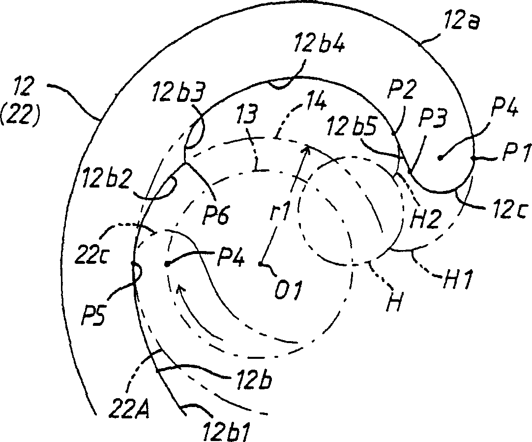
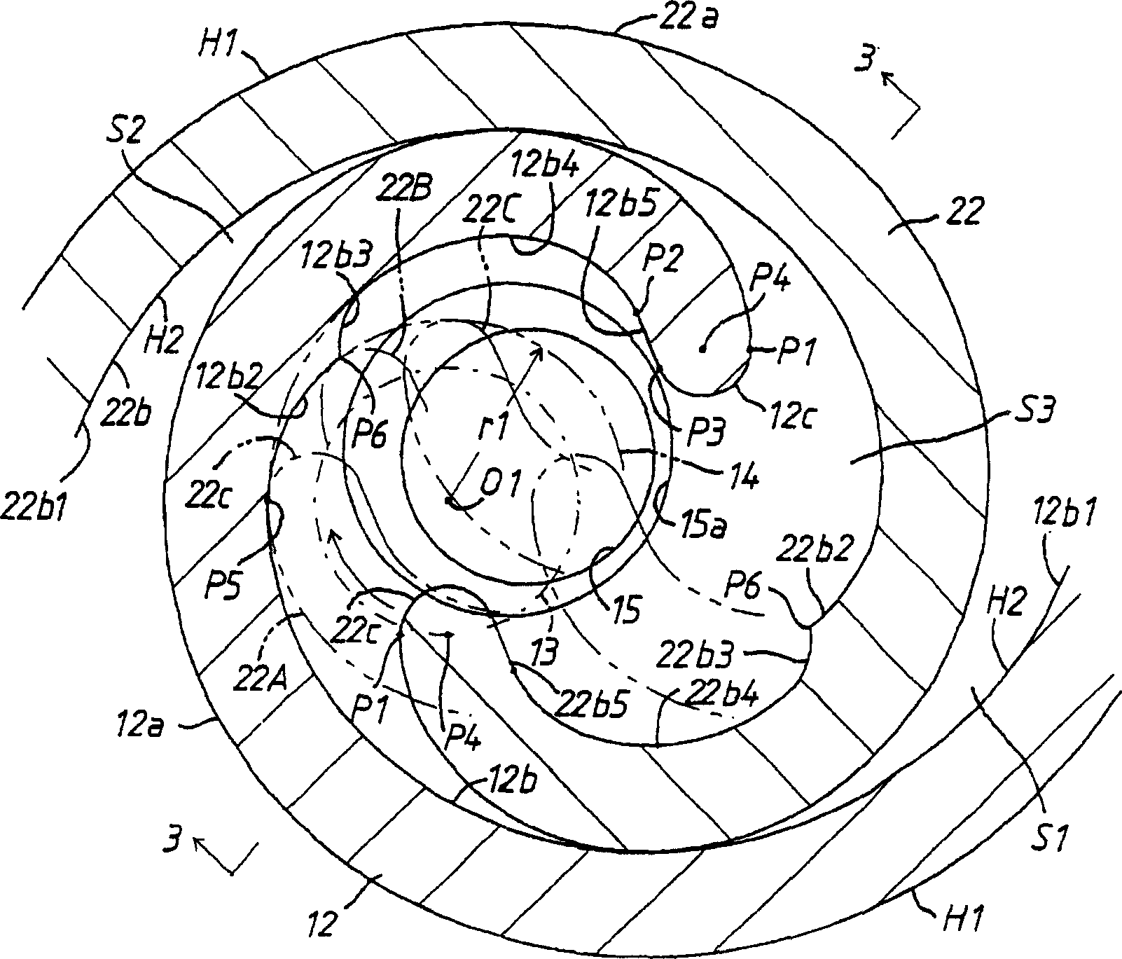
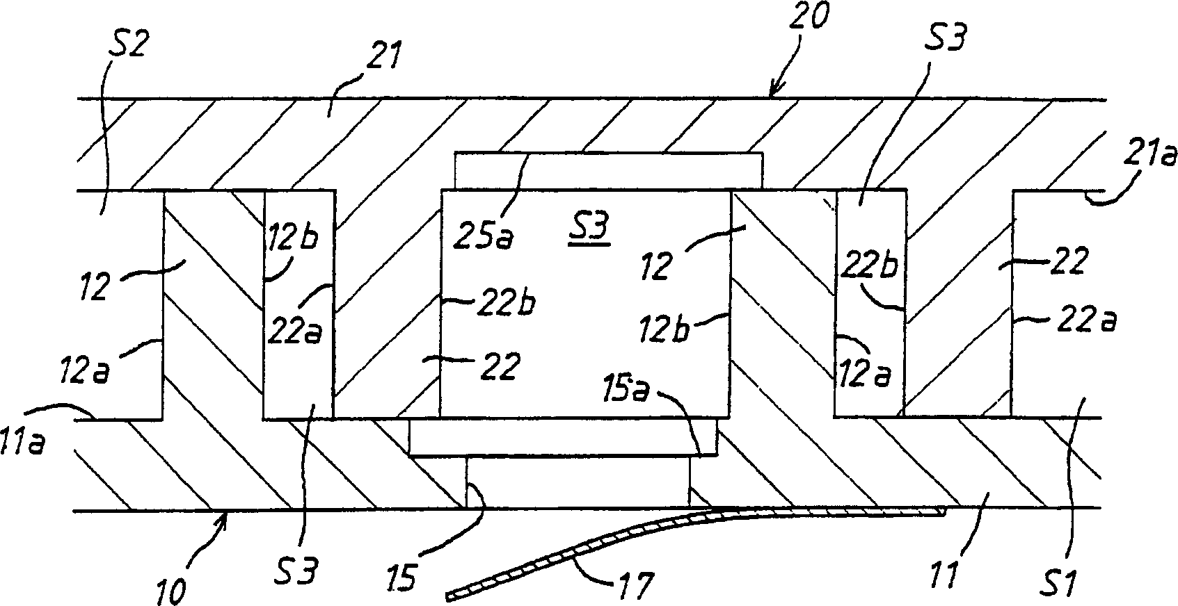
[0043] First, according to Figure 1 ~ Figure 3 , the first embodiment of the scroll compressor according to the present invention will be described. mainly as figure 2 and image 3 As shown, in the scroll compressor of this embodiment, the fixed scroll 10 formed by the fixed-side end plate 11 and the scroll-shaped fixed-side overlapping portion 12 erected on its inner surface 11 a , and the movable-side end plate 21 and a movable scroll 20 formed by a scroll-shaped movable side lap 22 erected on its inner surface 21a. The movable scroll 20 is assembled so that the outer peripheral portion of the inner surface 21a of the movable side end plate 21 and the upper end surface of a side peripheral wall (not shown) erected on the entire outer periphery of the fixed side end plate 11 are airtight and slidable. It abuts against the ground and rotates relative to the fixed scroll 10 without rotating. The two scrolls 10, 20 are combined such that the inner peripheral surface 12b of...


PUM


Abstract

The aim of the invention is to improve the compression ratio of a scroll compressor and decrease a power loss due to supercompression. A fixed scroll and a moving scroll on which spiral laps are erected on the inner surfaces of end plates and, respectively, are combined together and compression chambers moved to the central side as a volume is decreased are formed between the two laps. An inner peripheral surface of one lap consists of a first part composed of a part of an inner spiral surface slidably contacting with an outer peripheral surface of the other lap; a recessed circular arc-shaped second part continuously connected to the first part and slidably contacting with a small circular face at the tip on the central side of the other lap; a fourth part positioned further on the outside in a radial direction than the extension face of the second part and connected to a small circular arc face; and a third part discontinuously connected to the second part and rapidly outwardly separated from the extension face of the second part and connected to the fourth part.

Description

technical field [0001] The invention relates to a scroll compressor, in particular to a scroll compressor with improved compression ratio and reduced power loss caused by overcompression. Background technique [0002] As a scroll compressor in which power loss due to overcompression is reduced, there is a technology disclosed in Japanese Patent Application Laid-Open No. 2000-120565 (Patent Document 1). It is a scroll compressor that is a fixed scroll in which a scroll lap formed by an involute curve is erected on an end plate having a discharge hole in the center, and On the end plate opposite to the fixed scroll, the orbiting scroll with a scroll-shaped overlapping portion formed by an involute curve is vertically engaged to form a pair of compression chambers composed of a plurality of scrolls. The compressor is composed of: the initial rotation part of the overlapping part of each scroll, the outer circular arc smoothly connected by the front end of the overlapping part ...

Claims


Application Information

Patent Timeline
Patent Type & Authority Applications(China)
IPC IPC(8): F04C18/02
CPCF04C18/0215F04C18/0253F04C18/0269F04C29/0021F04C2210/26F04C2240/30Y10S415/00Y10S417/00
Inventor 渡边义实后藤和彦松本康臣
Owner AISIN SEIKI KK
Why Eureka
Try Eureka