
Transmitter stage

A transmitter and signal output technology, applied in transmission systems, digital transmission systems, high-frequency amplifiers, etc.

Inactive Publication Date: 2006-02-01
FRAUNHOFER GESELLSCHAFT ZUR FOERDERUNG DER ANGEWANDTEN FORSCHUNG EV
View PDF6 Cites 0 Cited by
  • Summary
  • Abstract
  • Description
  • Claims
  • Application Information

AI Technical Summary

Problems solved by technology

[0022] A disadvantage of the disclosure of patent EP 1211801 A2 is that the regulation of the output power is produced by a programmable amplifier in the feedback branch, which, together with a downstream jump-type controllable amplifier, must therefore provide a very highly dynamic output signal , but it is very small in the case of maximum output transmit power, and very large in other cases (i.e. minimum output power), and here it will be particularly close to the output signal amplitude of the transmit signal generator

Method used


Image

  • Transmitter stage
  • Transmitter stage
  • Transmitter stage

Examples


Embodiment Construction

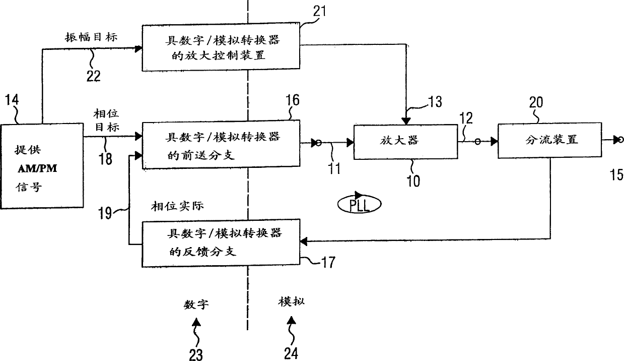
[0050] 1 is a circuit block diagram of a transmitter stage of the present invention which utilizes a power amplifier 10 having a signal input 11, a signal output 12 and an amplification control input 13 to transmit an amplitude and phase modulated signal.

[0051] The transmitter stage comprises providing means 14 to provide the amplitude and phase modulated signal, and is indicated by component number 14 in FIG. is propagated through the antenna and is coupled to the overall output 15 of the circuit.

[0052] The transmitter stage shown in FIG. 1 also includes a phase-locked loop (PLL) having a forward branch 16 and a feedback branch 17. The forward branch 16 includes a phase detector to compare the phase provided by the device 14 as a phase A phase representation of the target signal 18 and a phase actual signal 19 to provide an adjustment signal which is filtered through a loop filter and fed to a controllable oscillator coupled to the signal input of the power amplifier 1...


PUM


Abstract

The invention relates to a transmitter stage working according to the envelope restoration principle. Said stage comprises a device (14) for providing an amplitude representation and a phase representation of an amplitude and phase modulated signal which is to be sent, a phase control loop (PLL) with a feed-forward branch (16) and a feedback branch (17) and an amplification control device (21) which is embodied in such a manner that is can transform the amplitude representation into an amplification control signal which can be fed into in the amplification control input of a non-linear power amplifier. A digital / analog converter is arranged in the feed-forward branch (16). Additionally, an analog / digital converter is arranged in the feedback branch (17) such that the phase detector of the phase control loop is embodied in a digital form. The invention provides a transmitter stage which is precise and which can be economically implemented as a result of a large amount of digital signal processing.

Description

technical field [0001] The present invention relates to a transmitter stage, in particular to a transmitter stage according to the EDGE or UMTS specification that can transmit phase and amplitude modulated signals via amplifiers operating in the non-linear range. Background technique [0002] Mobile communication services have frequency band limitations. The channel bandwidth required for data transmission and the possible data rate are both key factors, which represent the efficiency of the transmission system, that is, in a It is necessary to increase the data rate as much as possible within the frequency band; currently there are many methods to increase the data rate of the same channel bandwidth, so as to have a more efficient message flow (message flow). [0003] In the past few years, the Global System for Mobile Communication (GSM) standard has been established in the field of mobile communication, and uses Gaussian Minimum Shift Keying (GMSK) modulation technology. ...

Claims


Application Information

Patent Timeline
Patent Type & Authority Applications(China)
IPC IPC(8): H03F1/02H03F3/19H04L27/20H04L27/34
CPCH04L27/2017H04L27/34
Inventor 郝曼·加法里拉尔夫·布而登斯基格拉尔德·乌尔里奇特
Owner FRAUNHOFER GESELLSCHAFT ZUR FOERDERUNG DER ANGEWANDTEN FORSCHUNG EV
Learn More