Vane speed regulator for electricity generation by wind power and ocean current

A technology of ocean current power generation and speed regulator, which is applied in the direction of wind turbine, wind motor combination, wind turbine control, etc. It can solve the problems of large speed regulation error, many wearing parts, complex structure, etc., and reach the range of stepless speed regulation Large, easy to repair, and easy to manufacture

Inactive Publication Date: 2006-02-08
陈祥水
View PDF2 Cites 22 Cited by
  • Summary
  • Abstract
  • Description
  • Claims
  • Application Information

AI Technical Summary

Problems solved by technology

But so far, the utilization efficiency of wind energy is still very low, because coal-fired fuel energy is currently used, and there is no idea that coal-fired fuel energy will bring serious pollution, resulting in global air pollution and global warming
At present, the known wind power generation or ocean current power generation has high power generation cost, low blade utilization efficiency, and difficult speed regulation function. At present, the speed regulation function and system structure used in wind power generation basically have: pumping station, oil cylinder, filter, servo oil cylinder , proportional valve, yaw gear, yaw motor, hydraulic brake has three parts: 1 low-speed

Method used


Image

  • Vane speed regulator for electricity generation by wind power and ocean current
  • Vane speed regulator for electricity generation by wind power and ocean current
  • Vane speed regulator for electricity generation by wind power and ocean current

Examples


Embodiment 1

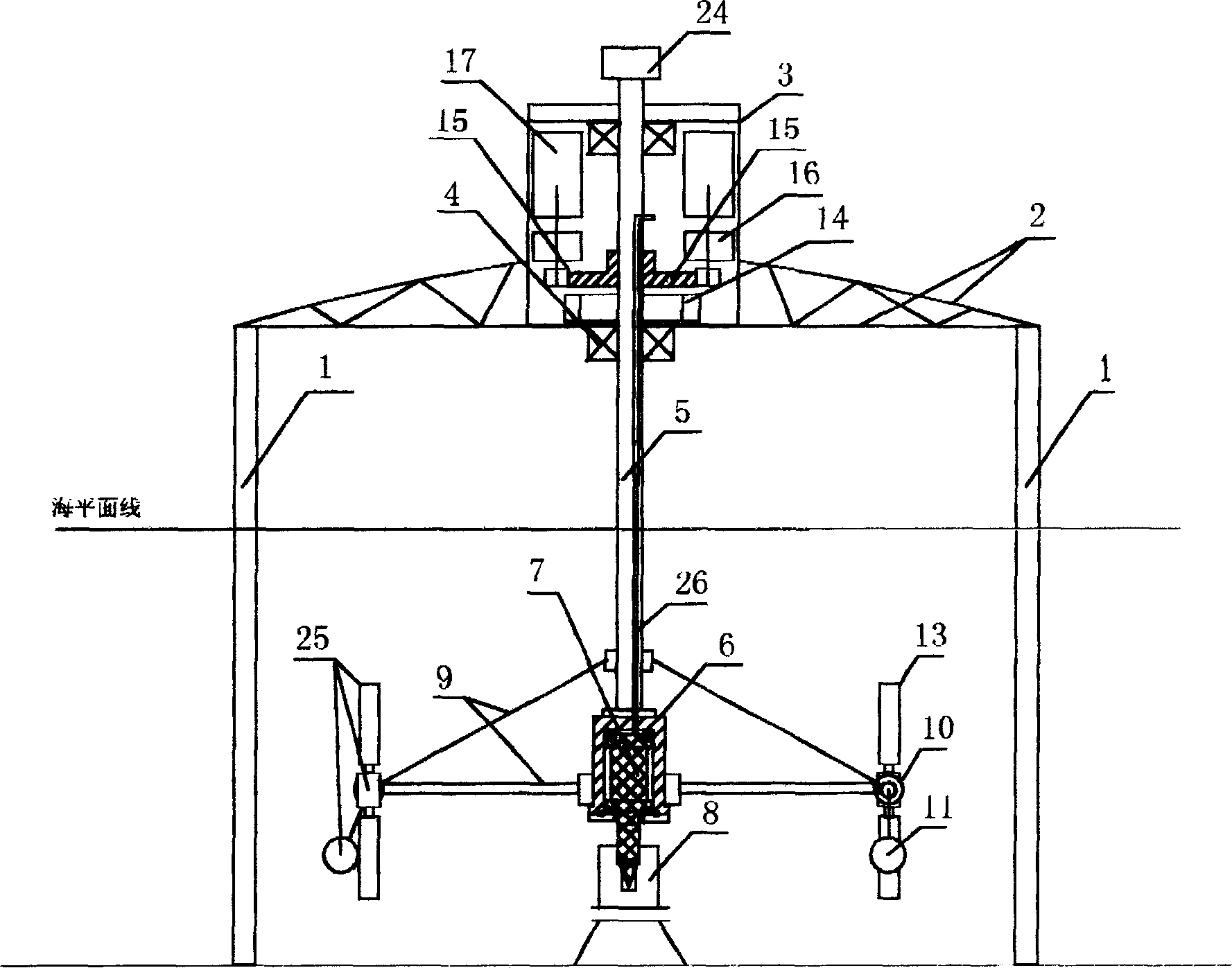
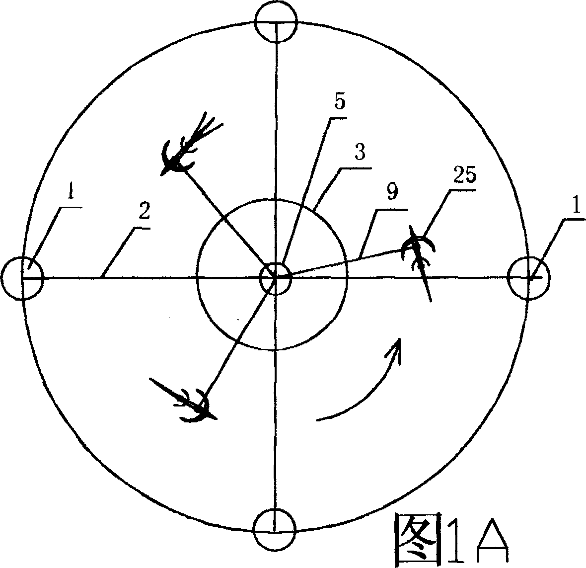
[0055] Shown in 4 / 8 page Fig. 2 is the structural diagram of the first embodiment of the triangular combined type, in accompanying drawing 2: tower base (1) connects drum (2) with slewing support structure or bearing (14) , the upper end of the drum (2) is provided with a blade shaft positioning (15), the upper end may also be provided with an upper fixed blade (16) and an upper bracket beam structure (17), and the lower end of the drum (2) is connected to the outside of the slewing bearing (8) The end is provided with a support beam (4), and the outer end of the support beam is connected to the speed regulating box (5), and the speed regulating box (5) is connected with the blade shaft (7) and the blade (3), and the speed regulating moving body (6) The running centrifugal gravity generates linkage to change the blade rotation angle to achieve high-precision speed regulation. The rotating cylinder (2) and the slewing support (8) are equipped with a transmission gear (9). The tr...

Embodiment 2

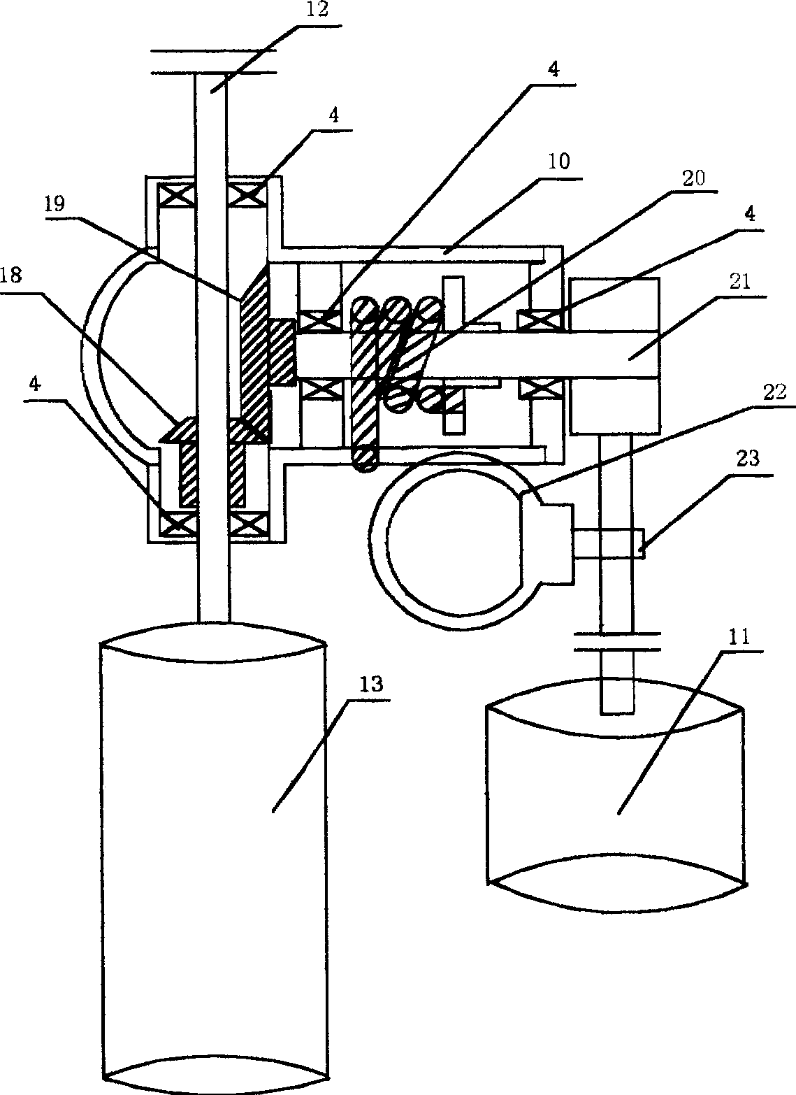
[0057] Shown in Fig. 3 on page 5 / 8 is the structural diagram of the second embodiment of the combined diameter type combined type, among which shown in accompanying drawing 3: the tower seat (6) is fixedly connected to the central fixed shaft (1), and is formed by a slewing support (9 ) or the bearing is movably connected to the rotating shaft (21), the upper and lower ends of the rotating shaft are provided with semicircular drag-reducing blades (2), and the outer end of the slewing bearing (9) is connected to the blades to form a fixed connection, and the middle end of the rotating shaft is connected with a support beam ( 8), the outer end of the support beam is provided with an automatic speed-regulating structure (22), including: the blade shaft (11), the connecting blade (10), and the centrifugal operation of the speed-regulating moving body (19) on the support beam, driving the transmission shaft (20) Upload the connecting piece, the transmission piece in the linkage spee...

Embodiment 3

[0059] Shown in Figure 4 on page 6 / 8 is the structure diagram of the third embodiment that can be opened or folded in the shape of an umbrella for ships. In Figure 4, the rotating shaft (1) is connected to the bearing (2), and the tower is connected (3), the rotating shaft is provided with a stay rope fixer (13), and the stay rope fixer (13) tightens the rope (12), and the umbrella shape structure is opened by the pulley (17) and the rope hook (11), and the lifting Crossbeam movable wheel (4), movable joint (5), connect support crossbeam (18), support crossbeam (18) outer end is provided with speed regulating box (6), the movable joint of blade shaft movable location (10) is opened, adjusts The speed box body (6) is equipped with a horizontal shaft upper transmission part that is movably connected to the actuator on the blade shaft (8). Blade (9) rotates blade angle, plays speed regulating effect, is provided with the braking structure (14) that shuts down on the rotating shaf...


PUM


Abstract

The wind electric and sea current power generation vane speed regulator has tower seat, fixed cross beam, machine room, bearing, rotation shaft, movable shaft fixer, fixed shaft seat, frame cross beam, speed regulating box, moving body, vane shaft, vanes, etc. connected successively. There are automatic speed regulating structure on the frame cross beam, conveying part on the speed regulating structure and executing part on the vane shaft. The present invention has the vanes rotating in designed direction to drive the power generator to generate electric power and has the moving body and vanes to complete automatic speed regulation. The present invention has wide stepless speed regulating range and high speed regulating precision as well as high power and efficiency.

Description

Technical field: [0001] The invention relates to a kind of safety device application which can obtain wind power generation and sea current (belonging to water flow or seawater flow of tidal fluctuation) power generation, and an automatic centrifugal speed regulating mechanism to keep the rotation speed stable, especially relates to air flow and organic Wherever water flows, power generation can be installed, especially to solve the current energy pollution and energy shortage. Background technique: [0002] In the centuries BC, the people of our country used wind power to lift water, irrigate, grind flour, pound rice, and use sails to propel ships forward. At that time, vertical axis wind turbines were also popular, and they are still in use today. But so far, the efficiency of wind energy utilization is still very low, because coal and fuel oil are currently used for energy, and there is no idea that coal and fuel energy will bring serious pollution, resulting in global a...

Claims


Application Information

Patent Timeline
IPC IPC(8): F03D7/06F03B15/00F03D9/00F03B13/00F03D9/25F03D9/32
CPCY02E10/226Y02E10/725Y02E10/20Y02E10/72Y02E10/74
Inventor 陈祥水
Owner 陈祥水
Why Eureka
Try Eureka