Thermostatic control system for instruments

A technology for constant temperature control and instrumentation, which is applied in the direction of temperature control, instruments, and instrument parts by electric means, and can solve problems such as reducing the reliability and safety of equipment use, easy aging and deterioration of the insulating sheath of wires, and short circuits. , to achieve the effect of increasing the ambient temperature range, improving the temperature display and control accuracy, and reducing the volume

Inactive Publication Date: 2006-02-08
CHANGCHUN INST OF OPTICS FINE MECHANICS & PHYSICS CHINESE ACAD OF SCI
View PDF0 Cites 14 Cited by
  • Summary
  • Abstract
  • Description
  • Claims
  • Application Information

AI Technical Summary

Problems solved by technology

The power supply voltage used by these temperature control devices is 220V. Due to the different materials used for the heating resistance wire and the circuit wire, it is easy to break the circuit at the junction of the heating resistance wire and the wire, and because the heating resistance wire is often in a heated state, the insulation of the wire The foreskin is easy to age and deteriorate, causing a short circuit in the circuit, causing the device to burn out, and reducing the reliability and safety of the equipment.

Method used


Image

  • Thermostatic control system for instruments
  • Thermostatic control system for instruments
  • Thermostatic control system for instruments

Examples


Embodiment Construction

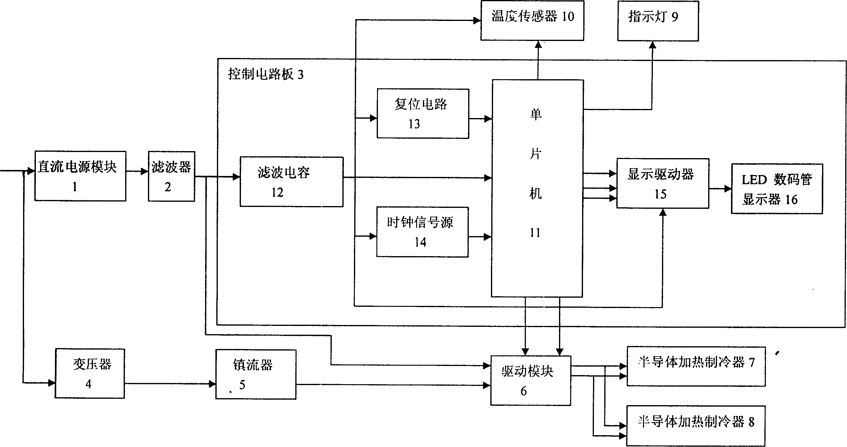
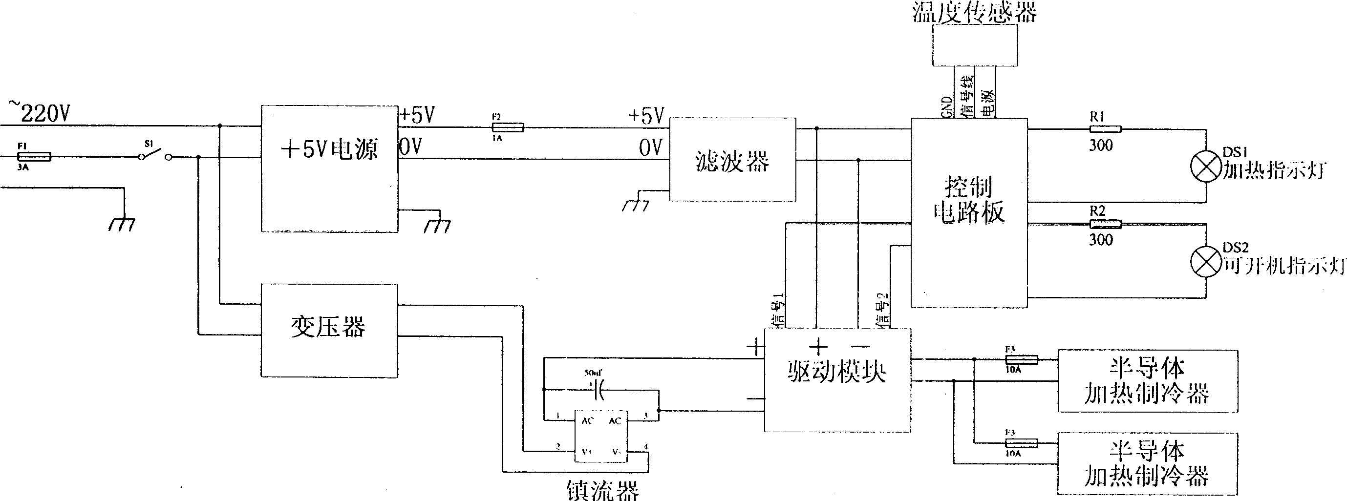
[0027] The present invention includes a DC power supply module 1 , a filter 2 , a control circuit board 3 , a transformer 4 , a ballast 5 , a drive module 6 , semiconductor heating refrigerators 7 and 8 , an indicator light 9 , and a temperature sensor 10 . like figure 2 The shown DC power supply module 1 adopts 4N1C-X5 type 5V / 1A power conversion module, filter 2 adopts model DL-2D1, transformer 4 adopts 220V AC voltage to convert 12V AC voltage, current 18A transformer, and ballast 5 KBPC3510W is adopted, and the drive module 6 is a motor drive module satisfying 30A, 250V, 50 / 60HZ. In order to increase heat dissipation and cooling area, the semiconductor heating refrigerators 7 and 8 are respectively inlaid on two aluminum plates with good thermal conductivity, and the temperature sensor 10 is a single-wire digital temperature sensor whose model is DS18B20.

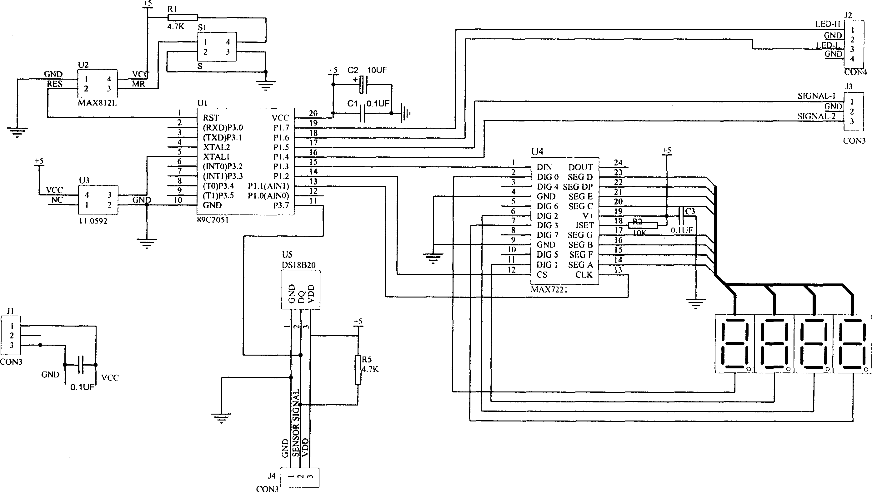
[0028] The control circuit board 3 includes a single chip microcomputer 11 , a filter capacitor 12 , a reset circui...


PUM


Abstract

The invention relates to an instrumental thermostatic control system in the field of temperature control technology, which comprises a dc power module, a filter, a control circuit plate, a converter, a current limiter, a driving module, a semi-conductor heating cooler, a guiding light and a temperature sensor. The dc power module is connected with the control circuit plate, the power input end of the driving module by the filter. The converter is connected with the current limiter and the driving module; the signal output ends of the control circuit plate are separately connected with the guiding light and the signal input end of the driving module. The output end of the driving module is connected with the heating cooler. The output end of the temperature sensor is connected with the digital signal input end of the control circuit plate.

Description

technical field [0001] The invention belongs to the technical field of temperature control, and relates to an electric heating device, in particular to a constant temperature control system for instruments. technical background [0002] The traditional temperature control method is conventional relay driven contactor control. Two temperature sensors are used to sense the change of ambient temperature. When the ambient temperature is lower than the temperature lower limit set by the temperature sensor, the circuit is connected and the resistance wire starts to heat. When the temperature exceeds the temperature upper limit set by the temperature sensor, the circuit is disconnected and the resistance wire stops heating. It can only achieve temperature control within a certain range, and it belongs to contact control, so it has the disadvantage of low control accuracy. During the control process, it is impossible to know the current temperature and whether the temperature contro...

Claims


Application Information

Patent Timeline
Patent Type & Authority Applications(China)
IPC IPC(8): G12B7/00G05D23/19G05D23/30
Inventor 王旻石基万
Owner CHANGCHUN INST OF OPTICS FINE MECHANICS & PHYSICS CHINESE ACAD OF SCI
Why Eureka
Try Eureka